INSTALL a new multifunction switch; REFER to Section . TEST the system for normal operation
The hazard flasher lamps are always on
Multifunction switch
INSTALL a new multifunction switch; REFER to Section . TEST the system for normal operation.
Pinpoint Tests
PINPOINT TEST J: THE TURN SIGNAL LAMPS ARE NEVER ON
Test Step
Result / Action to Take
J1 CHECK THE VOLTAGE TO THE ELECTRONIC FLASHER
Yes
GO to J2 .
No
REPAIR the circuit in question. TEST the system for normal operation.
Disconnect: Electronic Flasher C2141.
Key in ON position.
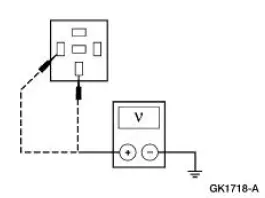
Measure the voltage between the following electronic flasher C2141 circuits, harness side and ground.
Pin 2, Circuit 1039 (BK/YE).
Pin 3, Circuit 383 (RD/WH).
Are the voltages greater than 10 volts?
J2 CHECK CIRCUIT 44 (LB)
Yes
GO to J3 .
No
REPAIR the circuit.
TEST the system for normal operation.
Key in OFF position.
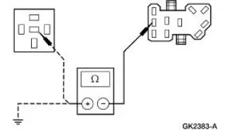
Disconnect: Multifunction Switch C202b.
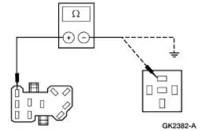
Measure the resistance between multifunction switch C202b Pin 44, Circuit 44 (LB), harness side and the electronic flasher C2141 Pin 1, Circuit 44 (LB), harness side; and between multifunction switch C202b Pin 44, Circuit 44 (LB), harness side and ground.
Is the resistance less than 5 ohms between the multifunction switch and the electronic flasher, and greater than 10,000 ohms between the multifunction switch and ground?
J3 CHECK THE CONTINUITY OF THE MULTIFUNCTION SWITCH
Yes
INSTALL a new electronic flasher.
TEST the system for normal operation.
No
INSTALL a new multifunction switch.
REFER to Section. TEST the system for normal operation.
Carry out the multifunction switch component test.
Refer to Wiring Diagrams Cell 149 for schematic and connector information.
Is the switch OK?
PINPOINT TEST K: THE HAZARD FLASHER LAMPS ARE NEVER ON
Test Step
Result / Action to Take
K1 CHECK THE VOLTAGE TO THE ELECTRONIC FLASHER
Yes
GO to K2 .
No
REPAIR the circuit.
TEST the system for normal operation.
Disconnect: Electronic Flasher C2141.
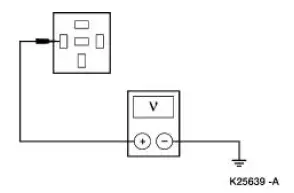
Measure the voltage between electronic flasher C2141 Pin 3, Circuit 383 (RD/WH), harness side and ground.
Is the voltage greater than 10 volts?
K2 CHECK CIRCUIT 385 (WH/RD)
Yes
GO to K3 .
No
REPAIR the circuit.
TEST the system for normal operation.
Disconnect: Multifunction Switch C202b.
Measure the resistance between multifunction switch C202b Pin 385, Circuit 385 (WH/RD), harness side and electronic flasher C2141 Pin 4, Circuit 385 (WH/RD), harness side; and between multifunction switch C202b Pin 385, Circuit 385 (WH/RD), harness side and ground.
Is the resistance less than 5 ohms between the multifunction switch and the electronic flasher, and greater than 10,000 ohms between the multifunction switch and ground?
K3 CHECK THE CONTINUITY OF THE MULTIFUNCTION SWITCH
Yes
INSTALL a new electronic flasher.
TEST the system for normal operation.
No
INSTALL a new multifunction switch; REFER to Section. TEST the system for normal operation.
Carry out the multifunction switch component test.
Refer to Wiring Diagrams Cell 149 for schematic and connector information.
Is the switch OK?
?
Test yourself
A quick Ford Mustang quiz: every answer comes with an explanation and a link to the manual page.