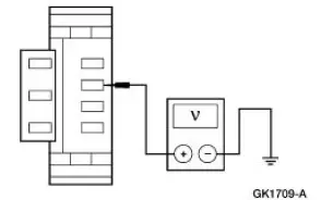
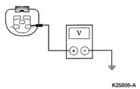
Refer to Wiring Diagrams Cell 85 , Headlamps for schematic and connector information.
Special Tool(s)
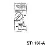
73III Automotive Meter or equivalent 105-R0057
Inspection and Verification
1. Verify the customer concern by operating the headlamps.
2. Visually inspect for the following obvious signs of mechanical and electrical damage.
Visual Inspection Chart
Mechanical
Electrical
Damaged headlamp switch (11654)
Damaged multifunction switch (13K359)
Battery junction box (BJB) fuse 2 (30A)
Central junction box (CJB) fuse(s):
38 (20A)
4 (7.5A) (RH)
10 (7.5A) (LH)
Damaged wiring harness
Loose or corroded connections
Headlamp bulb
3. If the concern is not visually evident, determine the symptom and proceed to Symptom Chart.
Symptom Chart
Condition
Possible Sources
Action
Both headlamps are inoperative
Battery junction box (BJB) fuse 2 (30A).
Headlamp switch.
Circuitry.
Multifun
Go To Pinpoint Test A .
The low beams are inoperative
Circuitry.
Multifunction switch.
Go To Pinpoint Test B .
The high beams are inoperative
Central junction box (CJB) fuse 38 (20A).
Circuitry.
Multifunction switch.
Go To Pinpoint Test C .
One low beam headlamp is inoperative
Central junction box (CJB) fuse (s):
10 (7.5A) (LH).
4 (7.5A) (RH).
Headlamp bulb.
Circuitry.
Go To Pinpoint Test D .
One high beam headlamp is inoperative
Headlamp bulb.
Circuitry.
Go To Pinpoint Test E .
The headlamps are on continuously
Headlamp switch.
Circuitry.
Multifunction switch
Go To Pinpoint Test F .
The flash-topass feature is inoperative
Circuitry.
Multifunction switch.
CHECK Circuit 196 (DB/OG) for an open. REPAIR if necessary. IF OK, INSTALL a new multifunction switch; REFER to Section. TEST the system for normal operation
Pinpoint Tests
PINPOINT TEST A: BOTH HEADLAMPS ARE INOPERATIVE
Test Step
Result / Action to Take
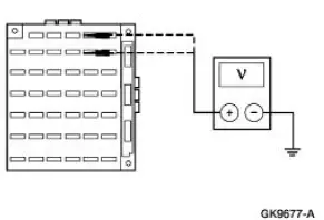
A1 CHECK THE VOLTAGE TO THE HEADLAMP SWITCH
Yes
GO to A2 .
No
REPAIR the circuit. TEST the system for normal operation.
Disconnect: Headlamp Switch C205.
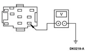
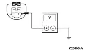
Measure the voltage between headlamp switch C205 Pin B1, Circuit 196 (DB/OG), harness side and ground.
Is the voltage greater than 10 volts?
A2 CHECK CIRCUIT 15 (RD/YE) FOR OPEN
Yes
RECONNECT headlamp switch C205. GO to A3 .
No
REPAIR the circuit. TEST the system for normal operation.
Disconnect: Multifunction Switch C202a.
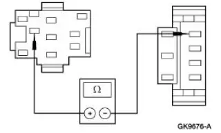
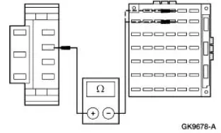
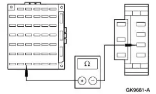
Measure the resistance between headlamp switch C205 Pin H, Circuit 15 (RD/YE), harness side and multifunction switch C202a Pin 15, Circuit 15 (RD/YE), harness side.
Is the resistance less than 5 ohms?
A3 CHECK THE VOLTAGE TO THE MULTIFUNCTION SWITCH
Yes
INSTALL a new multifunction switch; REFER to Section.
TEST the system for normal operation.
No
INSTALL a new headlamp switch; REFER to Lamp Switch-Headlamp in this section. TEST the system for normal operation.
Place the headlamp switch in the ON position.
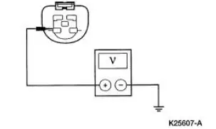
Measure the voltage between multifunction switch C202a Pin 15, Circuit 15 (RD/YE), harness side and ground.
Is the voltage greater than 10 volts?
PINPOINT TEST B: THE LOW BEAMS ARE INOPERATIVE
Test Step
Result / Action to Take
B1 CHECK THE VOLTAGE TO CJB FUSE 4 (7.5A) AND CJB FUSE 10 (7.5A)
Yes
Go To Pinpoint Test D .
No
GO to B2 .
Key in OFF position.
Place the multifunction switch in the low beam position.
Remove Fuse 4 (7.5A) and Fuse 10 (7.5A) from the CJB.
Place the headlamp switch in the ON position.
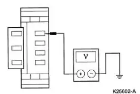
Measure the voltage between the following CJB fuse terminals and ground:
Fuse 4 connector.
Fuse 10 connector.
Are the voltages greater than 10 volts?
B2 CHECK CIRCUIT 13 (RD/BK) FOR OPEN
Yes
INSTALL a new multifunction switch; REFER to Section.
TEST the system for normal operation.
No
REPAIR the circuit. TEST the system for normal operation.
Disconnect: Multifunction Switch C202a.
Measure the resistance between multifunction switch C202a Pin 13, Circuit 13 (RD/BK), harness side and CJB Fuse 4 and Fuse 10.
Are the resistances less than 5 ohms?
PINPOINT TEST C: THE HIGH BEAMS ARE INOPERATIVE
Test Step
Result / Action to Take
C1 CHECK THE CIRCUIT 12 (LG/BK)
Yes
RECONNECT the LH headlamp (13008). GO to C2 .
No
REPAIR the circuit. TEST the system for normal operation.
Disconnect: LH Headlamp C1021.
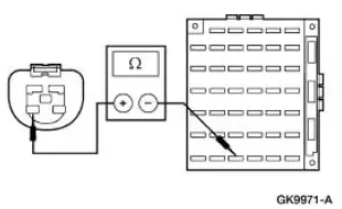
Measure the resistance between LH headlamp C1021 Pin 2, Circuit 12 (LG/BK), harness side and CJB Fuse 38 (20A).
Is the resistance less than 5 ohms?
C2 CHECK THE VOLTAGE TO CJB FUSE 38 (20A)
Yes
Go To Pinpoint Test E .
No
GO to C3 .
Place the headlamp switch in the ON position.
Place the multifunction switch in the high beam position.
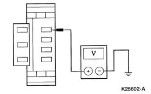
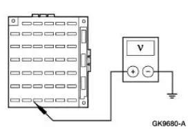
Measure the voltage between CJB Fuse 38 (20A) and ground.
Is the voltage greater than 10 volts?
C3 CHECK CIRCUIT 632 (GY/OG) FOR OPEN
Yes
INSTALL a new multifunction switch; REFER to Section. TEST the system for normal operation.
No
REPAIR the circuit. TEST the system for normal operation
Disconnect: Multifunction Switch C202a.
Measure the resistance between the CJB Fuse 38 (20A), and multifunction switch C202a Pin 12, Circuit 632 (GY/OG), harness side
Is the resistance less than 5 ohms?
PINPOINT TEST D: ONE LOW BEAM HEADLAMP IS INOPERATIVE
Test Step
Result / Action to Take
D1 CHECK THE VOLTAGE TO THE INOPERATIVE HEADLAMP BULB
Yes
INSTALL a new headlamp bulb; REFER to Bulb-Headlamp in this section. TEST the system for normal operation.
No
REPAIR the circuit. TEST the system for normal operation.
Disconnect: Inoperative Headlamp.
Place the headlamp switch in the ON position.
Place the multifunction switch in the low beam position.
Measure the voltage between RH headlamp C1041 Pin 3, Circuit 1056 (DB/LG), or LH headlamp C1021 Pin 3, Circuit 1055 (WH/LG), harness side and ground.
Is the voltage greater than 10 volts?
PINPOINT TEST E: ONE HIGH BEAM HEADLAMP IS INOPERATIVE
Test Step
Result / Action to Take
E1 CHECK THE VOLTAGE TO THE INOPERATIVE HEADLAMP BULB
Yes
INSTALL a new headlamp bulb; REFER to Bulb- Headlamp in this section.
TEST the system for normal operation.
No
REPAIR the circuit. TEST the system for normal operation.
Key in OFF position.
Disconnect: Inoperative Headlamp.
Place the headlamp switch in the ON position.
Place the multifunction switch in the high beam position.
Measure the voltage between LH headlamp C1021 Pin 2, Circuit 12 (LG/BK), or RH headlamp C1041 Pin 2, Circuit 12 (LG/BK), harness side and ground.
Is the voltage greater than 10 volts?
PINPOINT TEST F: THE HEADLAMPS ARE ON CONTINUOUSLY
Test Step
Result / Action to Take
F1 CHECK THE HEADLAMP SWITCH
Yes
GO to F2 .
No
INSTALL a new headlamp switch; REFER to Lamp Switch-Headlamp in this section. TEST the system for normal operation.
Key in OFF position.
Disconnect: Headlamp Switch C205.
Are the headlamps on?
F2 CHECK THE MULTIFUNCTION SWITCH
Yes
GO to F4 .
No
GO to F3 .
Disconnect: Multifunction Switch C202a.
Are the headlamps on?
F3 CHECK CIRCUIT 15 (RD/YE) FOR SHORT TO POWER
Yes
REPAIR the circuit. TEST the system for normal operation.
No
INSTALL a new multifunction switch; REFER to Section 211- 05 . TEST the system for normal operation.
Measure the voltage between multifunction switch C202a Pin 15, Circuit 15 (RD/YE), harness side and ground.
Is the voltage greater than zero volts?
F4 CHECK CIRCUIT 13 (RD/BK) FOR SHORT TO POWER
Yes
REPAIR the circuit. TEST the system for normal operation.
No
GO to F5 .
Remove Fuse 4 (7.5A) and Fuse 10 (7.5A) from the CJB.
Measure the voltage between multifunction switch C202a Pin 507, Circuit 13 (RD/BK), harness side and ground.
Is the voltage greater than 0 volts?
F5 CHECK CIRCUIT 1056 (DB, LG) FOR VOLTAGE
Yes
REPAIR Circuit 1056 (DB/LG).
TEST the system for normal operations.
No
REPAIR Circuit 1055 (WH/LG).
TEST the system for normal operations.
Disconnect: Headlamp C1041.
Measure the voltage between RH headlamp C1041 Pin 3, Circuit 1056 (DB/LG), harness side and ground.
Is the voltage greater than 0 volts?
?
Test yourself
A quick Ford Mustang quiz: every answer comes with an explanation and a link to the manual page.