Refer to Wiring Diagrams Cell 93 , Backup Lamps for schematic and connector information.
Special Tool(s)
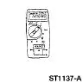 |
73III Automotive Meter or equivalent 105-R0057 |
Inspection and Verification
1. Verify the customer concern by operating the reversing lamps.
2. Visually inspect for obvious signs of mechanical and electrical damage; refer to the following chart:
Visual Inspection Chart
| Mechanical |
Electrical |
- Damaged digital transmission range (DTR) sensor (automatic transmission [A/T])
- Damaged reversing lamp switch (manual transmission [M/T])
|
- Blown central junction box (CJB) Fuse 11 (15A)
- Damaged wiring harness
- Loose or corroded connections
- Damaged reversing lamp
- Damaged DTR sensor (automatic transmission [A/T])
- Damaged reversing lamp switch (manual transmission [M/T])
|
3. If the concern is not visually evident, determine the symptom and proceed to Symptom Chart.
Symptom Chart
| Condition |
Possible Sources |
Action |
- The reversing lamps are inoperative
|
- CJB Fuse 11 (15A).
- Bulbs.
- Circuitry.
- DTR sensor (A/T).
- Reversing lamp switch (M/T).
|
|
- The individual reversing lamp is inoperative
|
|
|
- The reversing lamps are on continuously
|
- Circuitry.
- DTR sensor (A/T).
- Reversing lamp switch (M/T)
|
|
Pinpoint Tests
PINPOINT TEST R: THE REVERSING LAMPS ARE INOPERATIVE
| Test Step |
Result / Action to Take |
| R1 CHECK THE VOLTAGE TO THE DTR SENSOR (A/T) OR THE REVERSING LAMP SWITCH (M/T) |
Yes GO to R2 .
No
REPAIR the circuit. TEST the system for normal operation. |
- Key in OFF position.
- Disconnect: DTR Sensor C167 (A/T).
- Disconnect: Reversing Lamp Switch C169 (M/T).
- Key in ON position.
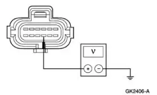
- If equipped with A/T, measure the voltage between DTR sensor C167 Pin 9, Circuit 1087 (OG), harness side and ground.
- If equipped with M/T, measure the voltage between reversing lamp switch C169, Circuit 1087 (OG), harness side and ground.
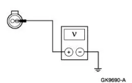
- Is the voltage greater than 10 volts?
|
| R2 CHECK CIRCUIT 140 (BK/PK) FOR OPEN |
Yes INSTALL a new DTR sensor (A/T) or reversing lamp switch (M/T); TEST the system for normal operation.
No
GO to R3 . |
- Key in OFF position.
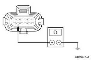
- If equipped with A/T, measure the resistance between DTR sensor C167 Pin 11, Circuit 140 (BK/PK), harness side and ground.
- If equipped with M/T, measure the resistance between reversing lamp switch C169, Circuit 140 (BK/PK), harness side and ground.
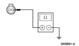
- Is the resistance less than 5 ohms?
|
| R3 CHECK REVERSING LAMPS GROUND |
Yes REPAIR Circuit 140 (BK/PK) for open. TEST the system for normal operation.
No
REPAIR the circuit. TEST the system for normal operation |
- Disconnect: Inoperative Reversing Lamp.
- Measure the resistance between LH reversing lamp C451, Circuit 1205 (BK), or RH reversing lamp C461, Circuit 1205 (BK), harness side and ground.
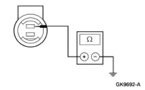
- Is the resistance less than 5 ohms?
|
PINPOINT TEST S: THE INDIVIDUAL REVERSING LAMP IS INOPERATIVE
| Test Step |
Result / Action to Take |
| S1 CHECK REVERSING LAMPS GROUND |
Yes REPAIR Circuit 140 (BK/PK) for open.
TEST the system for normal operation.
No
REPAIR the circuit.
TEST the system for normal operation. |
- Key in OFF position.
- Disconnect: Inoperative Reversing Lamp.
- Measure the resistance between LH reversing lamp C451, Circuit 1205 (BK), or RH reversing lamp C461, Circuit 1205 (BK), harness side and ground.
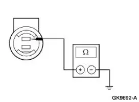
- Is the resistance less than 5 ohms?
|
PINPOINT TEST T: THE REVERSING LAMPS ARE ON CONTINUOUSLY
| Test Step |
Result / Action to Take |
| T1 CHECK THE CONTINUITY OF THE DTR SENSOR (A/T) OR THE REVERSING LAMP SWITCH (M/T) |
Yes REPAIR Circuit 140 (BK/PK) for short to battery.
TEST the system for normal operation.
No
INSTALL a new DTR sensor (A/T) or reversing lamp switch (M/T); TEST the system for normal operation. |
- Key in OFF position.
- Disconnect: DTR Sensor C167 (A/T).
- Disconnect: Reversing Lamp Switch C169 (M/T).
- Set the parking brake.
- Key in ON position.
- Select REVERSE.
- Are the reversing lamps illuminated?
|
?
Test yourself
A quick Ford Mustang quiz: every answer comes with an explanation and a link to the manual page.
Was this page helpful?