Engine Mechanical System
Engine and Transaxle Assembly Repair Procedures
In this manual: Engine Mechanical System
27steps
~162min
4/5difficulty
Done 0 of 27
Removal
|
|

- Remove the engine cover. (Refer to Engine and Transaxle Assembly - "Engine Cover")
- Remove the air duct and air cleaner assembly. (Refer to Intake and Exhaust System - "Air Cleaner")
- Remove the battery. (Refer to Engine Electrical System - "Battery")
- Remove the ECM (Engine Control Module). (Refer to Engine Control/Fuel System - "Engine Control Module (ECM)")
- Remove the battery tray. (Refer to Engine Electrical System - "Battery")
- Remove the engine compartment cover. (Refer to Engine and Transaxle Assembly - "Engine Compartment Under Cover")
- Drain the engine coolant. (Refer to Cooling System - "Engine Coolant")
- Disconnect the upper radiator hose (A).

- Disconnect the quick-connector of the lower radiator hose (A).


- After the hose is disconnected, remove the retainer clip (A), then disconnect the quick-connector.
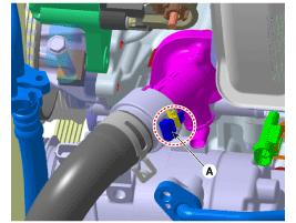
- Recover the refrigerant, then remove the high-pressure line and the low-pressure line. (Refer to Heating, Ventilation and Air Conditioning - "Compressor")
- Disconnect the transmission wiring harness connectors and the control cable from the transmission. (Refer to Automatic Transmission System - "Automatic Transmission")
- Disconnect the brake booster vacuum hose (A).

- Disconnect the heater hoses (A).
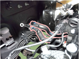
- Disconnect the fuel hose (A) and the hose (B) of the purge control solenoid valve (PCSV).
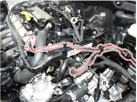
- Disconnect the wiring harness from the engine compartment.
- Remove the ground bolt (A).
- Disconnect the negative battery terminal connector (B).
- Disconnect the front wiring harness connector (C).
- Disconnect the printed circuit board unit (D).
- Disconnect the wiring protector (E).
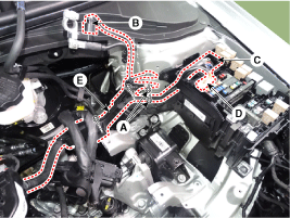
- Disconnect the positive battery cables (A).
- Disconnect the wiring protector (B).
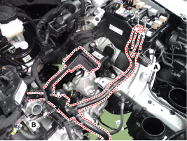
- Remove the front muffler. (Refer to Intake and Exhaust System - "Muffler")
- Remove the U-joint mounting bolts of the steering column. (Refer to Steering System - "Steering Column and Shaft")
- Remove the roller rod bracket (A). Tightening torque: Bolts (B): 49.0 ~ 64 N·m Nut (C): 107.9 ~ 128 N·m
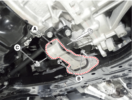
- Remove the roller rod bracket (A).
Tightening torque: 49.0 ~ 69 N·m

- Remove the suspension member. (Refer to Suspension System - "Suspension Member")
- Support the engine and transaxle assembly with a floor jack.
- Disconnect the ground cable (A).
Tightening torque: 10.8 ~ 13.7 N·m
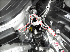
- Remove the engine mount support bracket (A). Tightening torque: Nut (B): 88.3 ~ 108 N·m Bolt, nut (C): 58.8 ~ 74 N·m

- Disconnect the ground line (A).
Tightening torque: 10.8 ~ 13.7 N·m
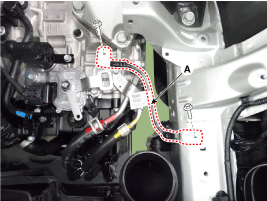
- Remove the service cover (A).
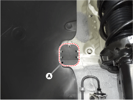
- Remove the bolts securing the transaxle support bracket (A).
Tightening torque: 88.3 ~ 108 N·m

- Remove the engine and transaxle assembly by lifting the vehicle.

- Before removing the engine and transaxle assembly, make sure that all hoses and wiring connectors are disconnected.
- When removing the engine and transaxle, be careful not to damage surrounding parts or body components.
Installation
Installation is performed in the reverse order of removal. Perform the following:- Adjust the shift cable.
- Adjust the throttle cable.
- Fill the engine with engine oil.
- Fill the transmission with fluid.
- Fill the radiator and the coolant reservoir with engine coolant.
- Set the heater control lever to the "HOT" position.
- Bleed air from the cooling system.
- (Refer to Cooling System - "Engine Coolant")
- Clean the battery terminals and cable terminals with sandpaper, reconnect them, then apply grease to prevent corrosion.
- Inspect for fuel leaks.
- After assembling the fuel line, turn the ignition switch ON (do not operate the starter) so that the fuel pump operates for about two seconds and pressurizes the fuel line.
- Repeat this procedure two or three times, then check all fuel line connections for leaks.
Test yourself
A quick Hyundai Elantra AD quiz: every answer comes with an explanation and a link to the manual page.
Was this page helpful?