Steering
Repair Procedures
In this manual: Steering
6steps
~36min
2/5difficulty
Done 0 of 6
General Inspection
After or before servicing the EPS system, perform the following troubleshooting and inspection procedure. Compare the system condition with the normal condition in the table below. If an abnormal symptom is found, perform the necessary measures and inspection.| Test Conditions | Symptoms | Assist Time |
Warning Light | Cause | Inspection Item | |
| IG ON / Engine ON / Stationary > IG OFF / Engine OFF / Stationary | Steering malfunction | - | - | - | Normal | |
| Steering assist is operating | 120 seconds | Light on | Ignition power is supplied even when IG is OFF. Steering angle not initialized |
 Check the IG power supply line.  Use a scan tool to initialize the steering wheel angle. |
||
| Light OFF | Ignition power is supplied even when IG is OFF. Steering angle not initialized & cluster malfunction. |
Check the cluster wiring. Check the ignition power supply line.  Use a scan tool to initialize the steering wheel angle. |
||||
| 70 seconds | Light on | CAN BUS OFF or EMS signals not received | Check the CAN communication line. | |||
| Light OFF | (CAN BUS OFF or EMS signals not received) and cluster malfunction | Check the CAN communication line. Check the cluster wiring. |
||||
| IG ON / Engine OFF / Stationary | - | Steering malfunction | - | - | - | - |
| Steering assist is operating | Duration | Light on | CAN BUS OFF or EMS signals not received | Check the CAN communication line. |
||
| Light OFF | (CAN BUS OFF or EMS signals not received) and cluster malfunction | Check the CAN communication line. Check the cluster wiring |
||||
| When the engine is running, IG remains ON but the engine stops. | Duration | Light on | CAN BUS OFF or EMS signals received | Check the CAN communication line. | ||
| 120 seconds | Light OFF | - | Normal | |||
| IG ON / Engine ON / Stationary | Steering malfunction | - | Light on | Malfunctions in EPS system power supply and ignition | Check the EPS system power supply and ignition lines. | |
| - | Light on | Diagnostic Trouble Code (DTC) is displayed | Use a scan tool to diagnose and troubleshoot. | |||
| Steering assist is operating | - | - | - | Normal | ||
| - | Light on | Diagnostic Trouble Code (DTC) is displayed | Use a scan tool to diagnose and troubleshoot. | |||
IG: Ignition; ASP: Absolute Steering Position; CAN: Controller Area Network; EMS: Engine Management System; ASP (Absolute Steering Position) calibration or EPS type recognition
|

- Connect the Data Link Connector (DLC) (16-pin), located under the driver's side crash pad lower panel, to the scan tool.
- Turn on the scan tool after turning the ignition switch ON.
- After selecting "Vehicle Model" and "System", select "ASP Calibration" on the GDS vehicle selection screen.
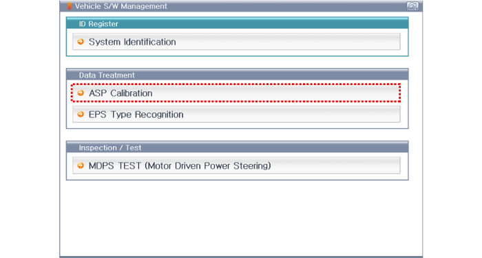
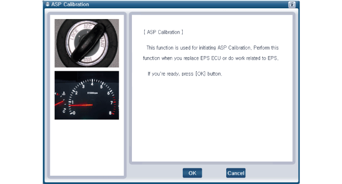
- Connect the Data Link Connector (DLC) (16-pin), located under the driver's side crash pad lower panel, to the scan tool.
- Turn on the scan tool after turning the ignition switch ON.
- After selecting "Vehicle Model" and "System", select "EPS Type Recognition" on the GDS vehicle selection screen.
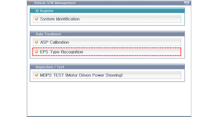
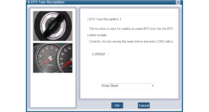
Test yourself
A quick Hyundai Elantra AD quiz: every answer comes with an explanation and a link to the manual page.
Was this page helpful?