Steering
Steering Column and Shaft Repair Procedures
In this manual: Steering
21steps
~126min
4/5difficulty
Done 0 of 21
Removal
- Disconnect the negative battery cable from the battery and wait at least 30 seconds.
- Turn the steering wheel so that the front wheels are in the straight-ahead position.
- Remove the driver airbag module (DAB).
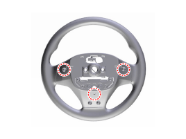

- Insert the tip of a flat-tip tool along the guide hole. (A 5 mm hex key is recommended.)
- With the tool inserted, apply light pressure. The airbag module can be removed easily.
- Disconnect the airbag module connector (A) and the horn connector (B).
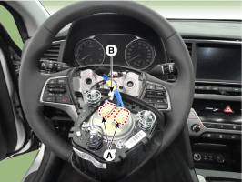
- Store the removed airbag module in a clean, dry place with the pad cover facing up.
- Disconnect the connector (A), then remove the steering wheel by loosening the lock bolt (A).
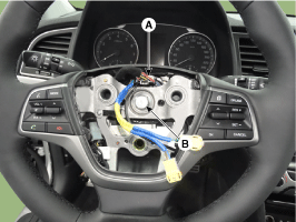
- Do not reuse the steering lock bolt.
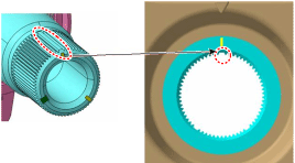
- When assembling, align the gear teeth as shown in the illustration below.
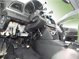
- Loosen the screw and remove the upper (A) and lower steering column covers (B).
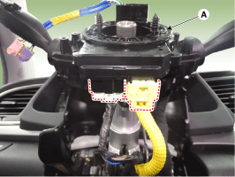
- Disconnect the connector, and then separate the clock spring (A).
- Disconnect the multifunction switch connector.
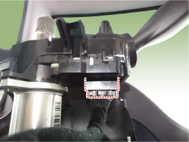
- Loosen the screw and remove the multifunction switch.
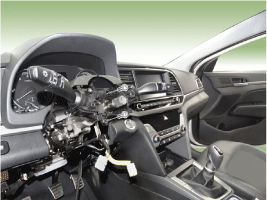
- Remove the lower driver airbag panel. (Refer to Body - "Driver Airbag Module")
- Remove the fixing clip, and then disconnect the wiring from the steering column.
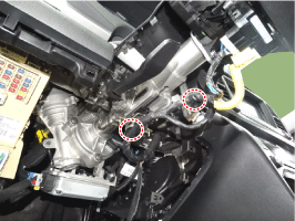
- Disconnect the MDPS ECU connector.
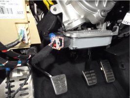
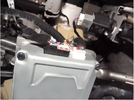
- Loosen the bolt (A) and disconnect the universal joint assembly from the steering gear.
Tightening torque: 32.4 ~ 37 N·m
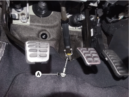
- Do not reuse the bolt.
- Lock the steering wheel in the straight-ahead position to prevent damage to the clock spring internal cable.
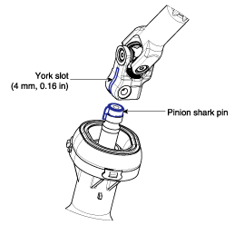
- During installation, insert the cotter pin into the groove of the universal joint as shown in the illustration below.
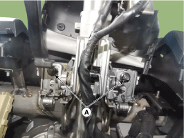
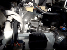
- Remove the steering column and EPS unit by loosening the mounting bolt (B) and nuts (A). Tightening torque: Nut: 25.0 ~ 29 N·m Bolt: 44.1 ~ 49 N·m
Disassembly
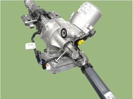
- Loosen the bolt (A) and then disconnect the universal joint assembly from the steering column assembly.
Tightening Torque: 49.0 ~ 59 N·m
- To reinstall, perform the removal procedure in reverse order.
- Assembly is the reverse of disassembly.
- Do not reuse the universal joint bolt. During installation, align the gear teeth as shown in the illustration below.
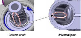
- Do not reuse the universal joint bolt. During installation, align the gear teeth as shown in the illustration below.
Installation
- To install, reverse the removal procedure.
- Connect the Data Link Connector (DLC) (16-pin), located under the driver's side crash pad lower panel, to the scan tool.
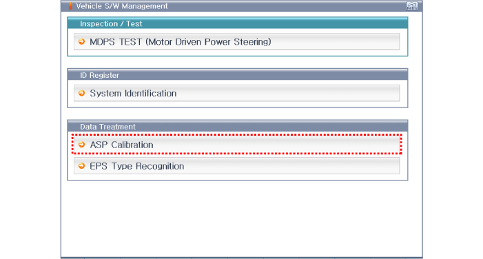
- Perform "ASP Calibration".
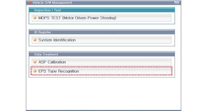
- Perform "EPS Type Recognition".
Test yourself
A quick Hyundai Elantra AD quiz: every answer comes with an explanation and a link to the manual page.
Was this page helpful?