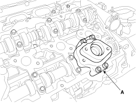
Remove the timing chain. (Refer to Valve Timing System - Timing Chain)
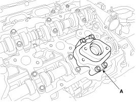
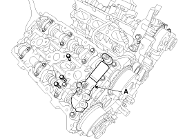
Remove the fuel pump bracket (A).
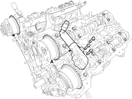
Remove the left exhaust camshaft oil control valve (OCV) (A).
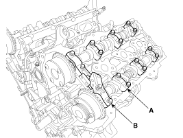
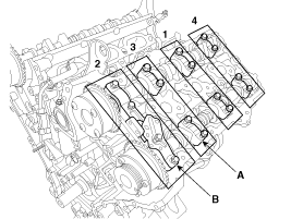
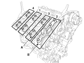
Remove the left camshaft cap (A) and thrust bearing cap (B).
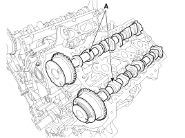
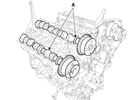
Remove the left camshaft assembly (A).
Remove the timing chain. (Refer to Valve Timing System - Timing Chain)
Remove the right exhaust camshaft oil control valve (OCV) (A).
Remove the right camshaft bearing cap (A) and thrust bearing cap (B).
Remove the right camshaft assembly (A).
Right Intake and Exhaust Camshaft
Inspection
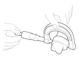
Inspect the cam lobes. Using a micrometer, measure the cam lobe height. Cam Lobe Height [Standard Value] Intake: 47.2 mm (1.8582 in) Exhaust: 45.8 mm (1.8031 in)If the cam lobe height is less than the standard value, replace the camshaft.
Inspect the camshaft journal surfaces for wear. If a journal is excessively worn, replace the camshaft.
Inspect the camshaft journal oil clearance.
Clean the camshaft bearing caps and journals.
Install the camshafts on the cylinder head.
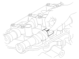
Place a strip of Plastigage on each camshaft journal.
Install the bearing cap (A) and thrust bearing cap (B) to the specified torque. Tightening Torque: Step 1: 5.8 N·m Step 2: 9.8 ~ 11.8 N·m
Do not rotate the camshaft.
Do not rotate the camshaft.
Be careful not to confuse the thrust bearing cap bolt (B) with the regular bearing cap bolt (A).
Remove the bearing caps.
Measure the width of the plastigage at its widest point. Oil clearance of bearing [Standard value] Intake Journal No.1: 0.027 ~ 0.057 mm (0.0010 ~ 0.0022 in) Journal No.2, 3, 4: 0.030 ~ 0.067 mm (0.0012 ~ 0.0026 in) Exhaust Journal No.1: 0.027 ~ 0.057 mm (0.0010 ~ 0.0022 in) Journal No.2, 3, 4: 0.030 ~ 0.067 mm (0.0012 ~ 0.0026 in)
A.
If the oil clearance is greater than specified, replace the camshaft.
B.
If the oil clearance is still greater than specified after replacing the camshaft, replace the bearing caps and the cylinder head assembly.
Completely remove the plastigage.
Remove the camshafts.
Inspect the camshaft end play.
Install the camshafts.
Install the bearing cap (A) and thrust bearing cap (B) and tighten to the specified torque. Tightening torque: Step 1: 5.8 N·m Step 2: 9.8 N·m
Do not rotate the camshaft.
Be careful not to confuse the thrust bearing cap bolt (B) with the regular bearing cap bolt (A).
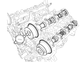
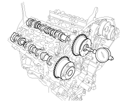
Using a dial indicator, measure the camshaft end play while moving the camshaft back and forth. Camshaft end play [Standard value]: 0.02 ~ 0.18 mm (0.0008 ~ 0.0071 in)
A.
If the end play is greater than specified, replace the camshaft.
B.
If the end play is still greater than specified after replacing the camshaft, replace the bearing caps and the cylinder head assembly.
Remove the camshafts.
Installation
Be careful when assembling the right/left bank and the intake/exhaust side.
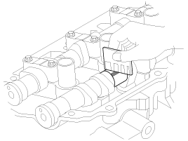
Align the keyway of the rear camshaft with the top surface of the head.
Apply a thin coat of engine oil to the camshaft journals.
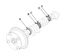
[Intake Camshaft]For camshaft identification, refer to the table below.
Displacement
Left bank
Right bank
3.8 L
A: 27 mm (1.0630 in) B: 27 mm (1.0630 in) C: 30 mm (1.1811 in) D: 30 mm (1.1811 in) E: 27 mm (1.0630 in)
A: 27 mm (1.0630 in) B: 27 mm (1.0630 in) C: 30 mm (1.1811 in) D: 27 mm (1.0630 in) E: 30 mm (1.1811 in)
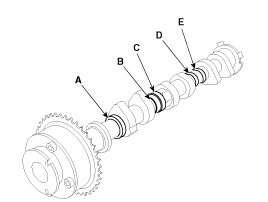
[Exhaust Camshaft]For camshaft identification, refer to the table below.
Displacement
Left bank
Right bank
3.8 L
A: - B: - C: - D: - E: 31 mm (1.2205 in)
A: 27 mm (1.0630 in) B: 27 mm (1.0630 in) C: 30 mm (1.1811 in) D: 30 mm (1.1811 in) E: -
Left Intake and Exhaust Camshaft
Install the left camshaft assembly (A).
Install the left camshaft cap (A) and thrust bearing cap (B). Tightening torque Step 1: 5.8 N·m Step 2: 9.8 ~ 11.8 N·m
Be sure to install the thrust bearing cap bolts and bearing cap bolts in the correct locations.
Be careful when assembling the right/left bank and the intake/exhaust side.
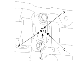
A: LH (Left), RH (Right) B: I (intake), E (exhaust) C: Journal number D: Front mark
When installing the camshaft bearing caps, turn the crankshaft so that the pistons are positioned at the center of the cylinder block to avoid unnecessary contact between the valves and pistons.
Install the left exhaust camshaft oil control valve (OCV) (A). (Refer to Engine Control/Fuel System - "CVVT Oil Control Valve (OCV)").
Tightening torque: 9.8 ~ 11.8 N·m
Install the fuel pump bracket (A).
Tightening torque: 18.6 ~ 24 N·m
Install the timing chain. (Refer to Timing System - Timing Chain)
Install the right camshaft assembly (A).
Install the right camshaft bearing cap (A) and thrust bearing cap (B). Tightening torque Step 1: 5.8 N·m Step 2: 9.8 ~ 11.8 N·m
Be sure to install the thrust bearing cap bolts and bearing cap bolts in the correct locations.
Install the bearing caps in the correct position, paying attention to the marks shown below.
A: LH (Left), RH (Right) B: I (intake), E (exhaust) C: Journal number D: Front mark
When installing the camshaft bearing caps, turn the crankshaft so that the pistons are positioned at the center of the cylinder block to avoid unnecessary contact between the valves and pistons.
Install the right exhaust camshaft oil control valve (OCV) (A).
Tightening torque: 9.8 ~ 11.8 N·m
Install the timing chain. (Refer to Timing System - Timing Chain)
Right Intake and Exhaust Camshaft
?
Test yourself
A quick Hyundai Genesis DH quiz: every answer comes with an explanation and a link to the manual page.