Use fender covers to avoid damaging painted surfaces.
To avoid damaging the cylinder head, wait until the engine coolant temperature drops below normal temperature (20 °C [68°F]) before removing it.
When handling the metal gasket, be careful not to bend the gasket or damage the gasket contact surface.
To avoid damage, carefully disconnect the wiring connectors by holding the connector body.
Label all wires and hoses to avoid incorrect connection.
Turn the crankshaft pulley so that the No. 1 piston is at top dead center.
Left Cylinder Head
Remove the left exhaust manifold. (Refer to Intake and Exhaust System - "Exhaust Manifold")
Remove the left camshaft. (Refer to Cylinder Head Assembly - "Camshaft")
Remove the water temperature control unit. (Refer to Cooling System - "Water Temperature Control Assembly")
Remove the fuel feed tube. (Refer to Engine Control Unit/Fuel System - "Fuel Supply System")
Remove the generator. (Refer to Engine Electrical System - "Generator")
Remove the left cylinder head assembly.
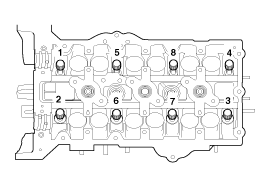
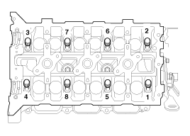
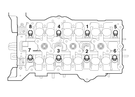
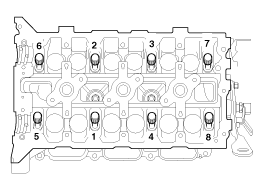
When loosening the cylinder head bolts, do not loosen the bolts completely one at a time. Loosen them in two or three steps, in the sequence shown below.
Cylinder head distortion or cracking may result if the bolts are loosened in the wrong order.
Lift the cylinder head off the dowels on the cylinder block and place the cylinder head on wooden blocks on the workbench.
Be careful not to damage the contact surfaces of the cylinder head and cylinder block.
Remove the cylinder head gasket.
Remove the right exhaust manifold. (Refer to Intake and Exhaust System - "Exhaust Manifold")
Remove the right camshaft. (Refer to Cylinder Head Assembly - "Camshaft")
Remove the water temperature control unit. (Refer to Cooling System - "Water Temperature Control Assembly")
Remove the fuel feed tube. (Refer to Engine Control Unit/Fuel System - "Fuel Supply System")
Remove the right cylinder head assembly.
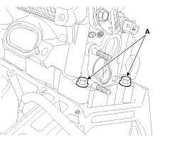
Remove the rear bolt of the right cylinder head (A). [3.8 L]
When loosening the cylinder head bolts, do not loosen the bolts completely one at a time. Loosen them in two or three steps, in the sequence shown below.
Cylinder head distortion or cracking may result if the bolts are loosened in the wrong order.
Lift the cylinder head off the dowels on the cylinder block and place the cylinder head on wooden blocks on the workbench.
Be careful not to damage the contact surfaces of the cylinder head and cylinder block.
Remove the cylinder head gaskets.
Right Cylinder Head
Disassembly
Identify the MLAs, valves, and valve springs as they are removed so that each component can be reinstalled in its original position.
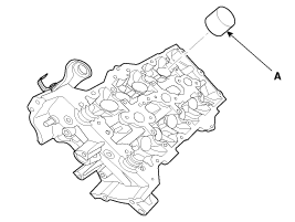
Remove the mechanical lash adjusters (MLA) (A).
Remove the valves.
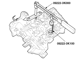
Using SST (09222-3K000, 09222-3K100), compress the valve spring and remove the valve cotter (keeper).
Remove the spring retainer.
Remove the valve spring.
Remove the valve.
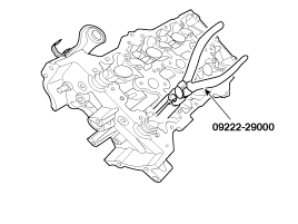
Using SST (09222-29000), remove the valve stem seal.
Do not reuse the old valve stem oil seals.
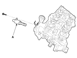
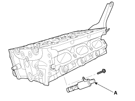
Remove the left/right intake camshaft oil control valve (OCV) (A).
Inspection
Cylinder head cover
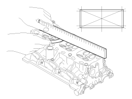
Inspect for flatness. Using a precision straightedge and feeler gauge, measure the flatness of the surface where the cylinder head contacts the manifold. Cylinder head gasket surface flatness Standard: Less than 0.05 mm (0.002 in) [Less than 0.02 mm (0.0008 in) / 150x150] Manifold gasket surface flatness Standard: Less than 0.01 mm (0.0004 in) [Less than 0.03 mm (0.001 in) / 110x110]
Inspect for cracks. Check the combustion chamber, intake ports, exhaust ports and cylinder head surface for cracks. If any cracks are found, replace the cylinder head.
Inspect the valve stems and valve guides.
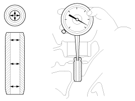
Using a caliper gauge, measure the inside diameter of the valve guide. Valve guide inside diameter Intake/Exhaust: 5.500 - 5.512 mm (0.2165 - 0.2170 in)
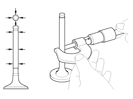
Using a micrometer, measure the diameter of the valve stem. Valve stem outside diameter Intake: 5.465 - 5.480 mm (0.2151 - 0.2157 in) Exhaust: 5.458 - 5.470 mm (0.2149 - 0.2153 in)
To calculate the valve stem-to-guide clearance, subtract the valve guide inside diameter from the valve stem outside diameter. Valve stem-to-guide clearance [Standard] Intake: 0.020 - 0.047 mm (0.0008 - 0.0018 in) Exhaust: 0.030 - 0.054 mm (0.0012 - 0.0021 in) [Limit] Intake: 0.07 mm (0.0027 in) Exhaust: 0.09 mm (0.0035 in)
Inspect the valves.
Check the valve face angle.
Inspect the valve face for wear. If wear is excessive, replace the valve.
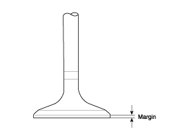
Check the valve head margin thickness. If the margin is less than the minimum, replace the valve. Standard Intake: 1.56 - 1.86 mm (0.06142 - 0.07323 in) Exhaust: 1.73 - 2.03 mm (0.06811 - 0.07992 in)
Check the valve length.
Length Intake: 105.27 mm (4.1445 in) Exhaust: 105.50 mm (4.1535 in)
Check the valve stem tip for wear. If the valve stem tip is worn, replace the valve.
Inspect the valve seats.
Check the valve seat for signs of overheating and improper contact with the valve face. If the valve seat is worn, replace the cylinder head.
Before resurfacing the seat, check the valve guide for wear. If the valve guide is worn, replace the cylinder head.
Resurface the valve seat using a seat grinder or cutter. The valve seat contact width must meet the specifications and be centered on the valve face.
Inspect the valve springs.
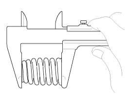
Using a steel square, measure the valve spring squareness.
Using a caliper gauge, measure the free length of the valve spring. Valve spring Standard free height: 46.2 mm (1.8189 in) Angle of squareness: Max. 1.5°
Inspect the MLA. Using a micrometer, measure the outside diameter of the MLA.
Using a caliper gauge, measure the inside diameter of the MLA bore in the cylinder head. MLA bore inside diameter Intake/Exhaust: 35.000 - 35.025 mm (1.3779 - 1.3789 in)
Subtract the MLA outside diameter from the MLA bore inside diameter. MLA-to-bore clearance [Standard] Intake/Exhaust: 0.020 - 0.061 mm (0.0008 - 0.0024 in) [Limit] Intake/Exhaust: 0.07 mm (0.0027 in)
Valve and Valve Spring Mechanical Lash Adjuster (MLA)
Installation
Thoroughly clean all parts to be assembled.
Before installing parts, apply new engine oil to all sliding and rotating surfaces.
Replace the valve stem oil seals with new ones.
Install the valves.
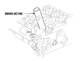
Using SST (09222-3C100), install a new oil seal.
Do not reuse old valve stem oil seals. Incorrect seal installation may cause oil to leak through the valve guides.
Install the valve stem seal so that it fully covers the head surface.
After applying engine oil to each valve stem end, install the valve, valve spring and spring retainer.
When installing the valve spring, place the painted end toward the spring retainer.
Using SST (09222-3K000, 09222-3K100), compress the spring and install the valve cotters (keepers). After installing the valves, make sure the cotters are properly seated before releasing the valve spring compressor.
Lightly tap the end of each valve stem two or three times with a soft hammer or the wooden handle of a hammer to make sure the valve and cotters are seated correctly.
Install the mechanical lash adjusters (MLA). Make sure the MLA rotates smoothly by hand.
The MLA can be reinstalled in its original position. However, the valve clearance must be checked and adjusted accordingly before installing the cylinder head on the cylinder block. Refer to General Information in EM for valve clearance inspection and adjustment.
Install the left/right intake camshaft oil control valve (OCV) (A).
Tightening torque: 9.8 ~ 11.8 N·m
Install the OCV with the gray connector to the right bank.
Install the OCV with the black connector to the left bank.
If an OCV has been dropped, do not reuse it.
Keep the OCV clean.
Do not hold the OCV sleeve during service.
When installing the OCV to the engine, do not move the engine by holding the OCV connector.
Installation
Left Cylinder Head
Thoroughly clean all parts to be assembled.
Always use a new cylinder head gasket and manifold gasket.
Always use new cylinder head bolts. The cylinder head bolts are torque-to-yield bolts, designed to stretch permanently beyond the elastic limit when tightened. If the bolts are removed and reused, they may break or fail to maintain clamping force.
The cylinder head gasket is a metal gasket. Be careful not to bend it.
Turn the crankshaft and set the No. 1 piston to top dead center (TDC).
Install the left cylinder head.
A.
The sealant application areas on the cylinder head and cylinder block must be cleaned of engine oil and old sealant.
B.
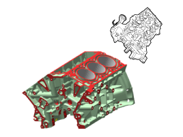
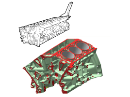
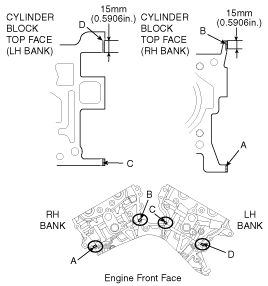
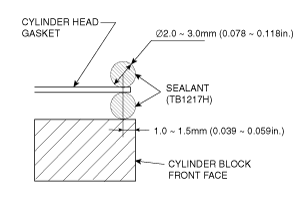
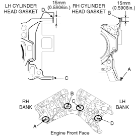
Apply sealant to the top surface of the cylinder block before installing the cylinder head gaskets. Assembly must be completed within 5 minutes after applying sealant.
Refer to the illustration below to apply sealant.
Bead width: 2.0 - 3.0 mm (0.078 - 0.118 in) Sealant application points: 1.0 - 1.5 mm (0.039 - 0.059 in) from the block surface Recommended sealant: THREE BOND 1217H liquid gasket
C.
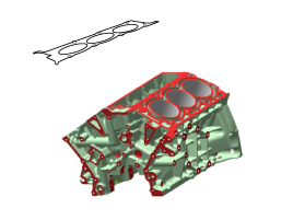
Apply sealant to the cylinder head gaskets after installing the gaskets on the cylinder block. Complete the assembly within 5 minutes after applying the sealant.
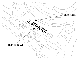
Pay attention to the installation direction.
D.
Install the left cylinder head.
Remove any sealant that has squeezed out after installing the cylinder heads.
Install the left cylinder head bolts.
Do not apply engine oil to the threads or under the heads of the cylinder head bolts.
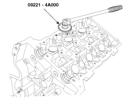
Using SST (09221-4A000): When installing the cylinder head, do not tighten the bolts fully in one pass. Tighten them in two or three steps in the sequence shown below.
Always use new cylinder head bolts. The cylinder head bolts are torque-to-yield bolts, designed to stretch permanently beyond the elastic limit when tightened. If the bolts are removed and reused, they may break or fail to maintain clamping force.
Install the generator. (Refer to Engine Electrical System - "Generator")
Install the fuel supply tube. (Refer to Engine Control/Fuel System - "Fuel Delivery System")
Install the water temperature control unit. (Refer to Cooling System - "Water Temperature Control Assembly")
Install the left camshaft. (Refer to Cylinder Head Assembly - "Camshaft")
Install the left exhaust manifold. (Refer to Intake and Exhaust System - "Exhaust Manifold")
Install the right cylinder head.
A.
The sealant application areas on the cylinder head and cylinder block must be cleaned of engine oil and old sealant.
B.
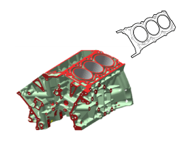
Apply TB 1217H sealant to the top surface of the cylinder block before installing the cylinder head gaskets. Complete the assembly within 5 minutes after applying the sealant.
Refer to the illustration below to apply sealant.
Bead width: 2.0 - 3.0 mm (0.078 - 0.118 in) Sealant application points: 1.0 - 1.5 mm (0.039 - 0.059 in) from the block surface Recommended sealant: THREE BOND 1217H liquid gasket
C.
Apply sealant to the cylinder head gaskets after installing the gaskets on the cylinder block. Complete the assembly within 5 minutes after applying the sealant.
Pay attention to the installation direction.
D.
Install the right cylinder head.
Remove any sealant that has squeezed out after installing the cylinder heads.
Install the right cylinder head bolts.
Do not apply engine oil to the threads or under the heads of the cylinder head bolts.
When installing the cylinder head bolts and plate washers, tighten them in two or three steps in the sequence shown below.
Always use new cylinder head bolts. The cylinder head bolts are torque-to-yield bolts, designed to stretch permanently beyond the elastic limit when tightened. If the bolts are removed and reused, they may break or fail to maintain clamping force.