Body Electrical System
Description and Operation
In this manual: Body Electrical System
8steps
~53min
3/5difficulty
1special tools
Done 0 of 8
Description
System Operation: The system is designed to help recognize the lane ahead and give a lane departure warning signal when the vehicle begins to drift out of its lane, using the camera image and vehicle signal information. Typical operating conditions of the LKAS controller. Note that the operating conditions are adapted to customer requirements.- Vehicle speed within 60 km/h – 200 km/h
- Lane markings are clearly visible.
- Driver does not overload the system by applying excessive torque to the steering wheel.
- Turn signals (including hazard warning signals) are off.
- Lane width from 2.7 m to 4.2 m.
- Lane curvature greater than 250 m.
- Absolute lateral acceleration of the vehicle < 2.5 m/s2.
- Driver's hands on the steering wheel.
- Vehicle does not exceed the lane boundaries by more than 0.3 m.
- Absolute steering wheel angle < specified value (for example, 90 degrees)
- Maximum allowable application time of maximum torque is not exceeded. (90 seconds)
- Reverse or city mode EPS is not activated.
- No system malfunctions are present.
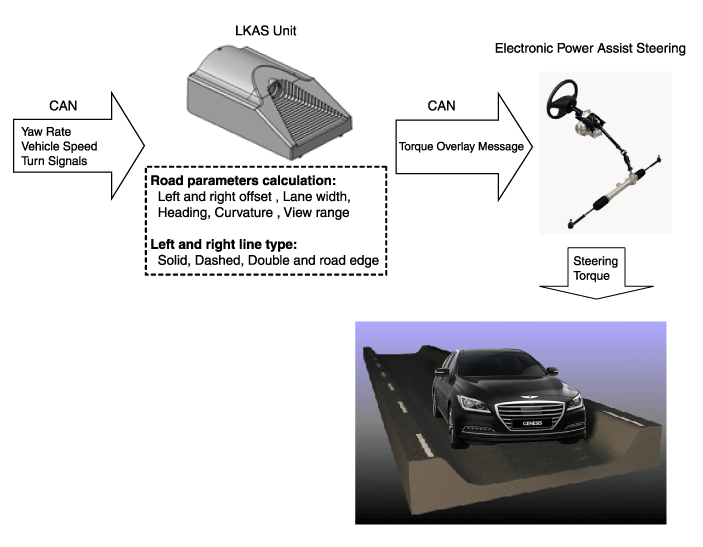
- Warning Method
- Cluster Display Symbols
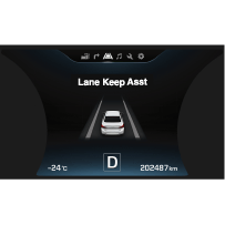
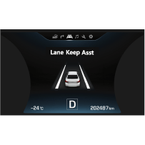
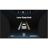
Lane not detected Lane detected and LKAS is on Right-side departure 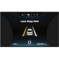
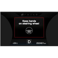
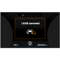
Left-side departure Hold the steering wheel LKAS canceled
? The displayed symbol and period vary depending on the vehicle LCD and the warning. (The light flashing period can be adjusted.)
LKAS may recognize continuous lines as lane markings and has limited lane recognition capability on sharp road curves. In addition, the system may malfunction in the following cases:
- Lane markings are missing or worn (lane could not be identified).
- Poor visibility due to bad weather conditions.
- Low light or sudden changes in external lighting conditions.
- Sharp road curves (curvature radius less than 250 m).
- Sidewalks and other separating structures along the edge of the lane.
- Dirty windshield (poor camera visibility).
- Cluster Display Symbols
- Recommendations for Selecting a Suitable Target. The following conditions are required for successful completion of the LKAS Service Calibration-Static procedure:
A. The target surface (SST: 09890-3V100) must be perpendicular to the camera in both horizontal and vertical orientation to maintain a maximum roll of 1°. B. Target is mounted on a rigid backing material to meet flatness requirements. C. The target must have reflective (not faded or poorly colored) markings so that it does not show lane features. D. The size must be 30 cm wide and 100 cm high. E. Installation area must NOT have cross-hatching or text markings near the target. F. Target must be well lit for optimal operation using constant lighting. There must be no continuous shadows on the target. 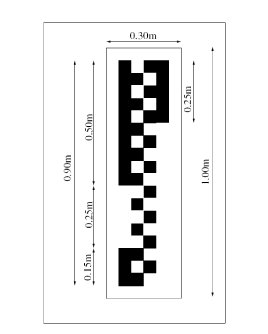
- Automatic Calibration Service Target Procedure
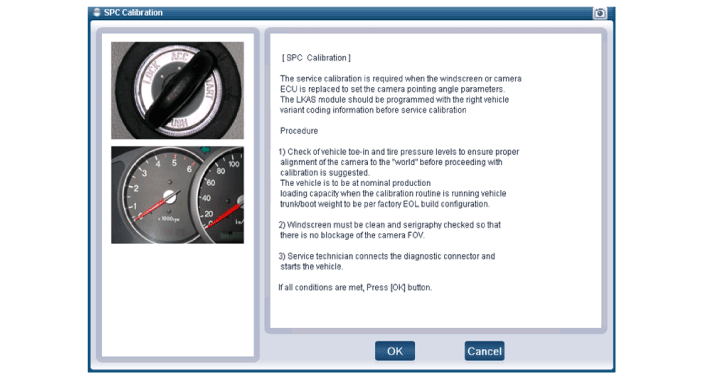
- Check the wheel alignment and tire pressures to ensure accurate camera calibration. The vehicle must be at its rated production load capacity when the calibration procedure is run.
- Keep the windshield clean and make sure the camera is not blocked by the silk-screened area.
- The service technician connects the diagnostic tool to the vehicle and starts the calibration procedure. The camera module must not be activated by pressing a switch.
- The service calibration procedure may not work correctly if there are any malfunctions in the LKAS system.
- If replacing the ECU: the service technician initiates the EOL variant code setting.
- The service technician aligns either the vehicle to the target or the target to the vehicle. (Near target calibration)
A. The lower edge of the target must be at a height of 90 cm ± 2 cm from the ground and aligned with the horizontal axis of the camera lens. B. Position the target along the longitudinal axis (centerline) of the vehicle within ± 5 cm of the target center. C. The vehicle bumper must be within 10 cm of the specified vertical plane, and the horizontal plane of the vehicle must be within 1° of the target horizontal plane for the first "near" image collection. 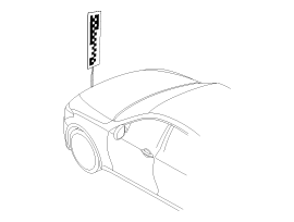
- First check the target installation position, then select "OK" on the diagnostic tool (GDS).
- The service technician aligns either the vehicle to the target or the target to the vehicle. (Far target calibration)
A. The lower edge of the target must be at a height of 90 cm ± 2 cm from the ground and aligned with the horizontal axis of the camera lens. B. Position the target along the longitudinal axis (centerline) of the vehicle within ± 5 cm of the target center. C. The vehicle bumper must be within 1.2 m ± 20 cm of the bumper and the target horizontal plane within 1.2° of the initial target location for the second "far" image collection. - Check the position of the second target, then select "OK" on the diagnostic tool (GDS).
- Perform the automatic service point target calibration procedure on the diagnostic tool (GDS).
- Clear all DTCs.
- Turn the ignition OFF and then ON.
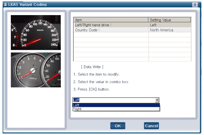
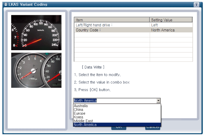
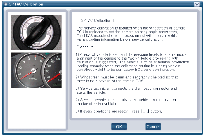
- Minimum vehicle speed: more than 22 mph
- Minimum driving distance: more than 1.1 miles
- Lane markings must be clearly visible on both sides. (LKAS may not detect faded lane paint.)
- The road must not have sharp curves (radius of curvature less than 820 ft).
- There must be no curbs or other barriers along the edge of the lane.
|
Service Point Calibration (SPC) Procedure
- Connect the VCI DLC cable to the data link connector located under the left side of the instrument panel.
- On the system screen, select "LKAS" and press "OK".
- Go to the "Vehicle Software Management" tab. Select "SPC Calibration" under "Data Processing".
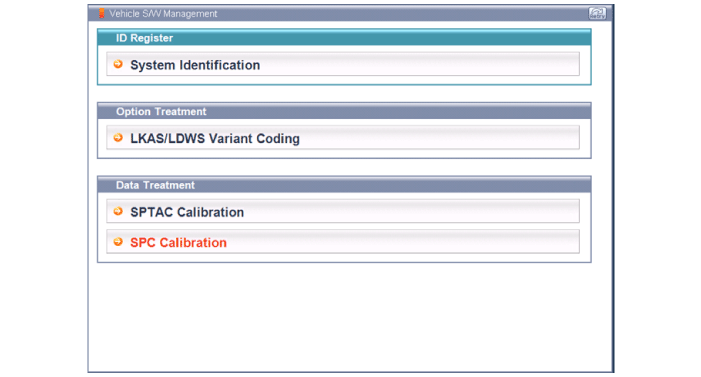
- Follow the GDS prompts and perform all system checks before continuing. When ready to start driving, press "OK".
- While driving on a road suitable for LKAS calibration, the GDS will display the calibration status.
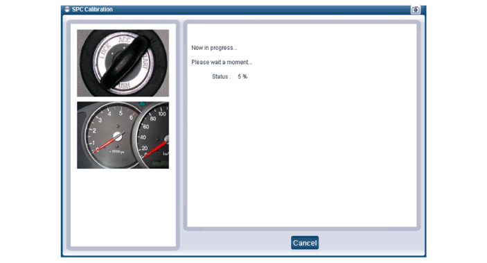

- If the vehicle leaves a straight road, enters winding roads, or stops, calibration progress is retained and the calibration process resumes when the vehicle returns to straight roads.
- Actual driving time depends on traffic and road conditions.
- If calibration is not completed within ten minutes, the calibration process fails. In this case, the calibration process must be repeated from the first phase.
Test yourself
A quick Hyundai Genesis DH quiz: every answer comes with an explanation and a link to the manual page.
Was this page helpful?