Loosen the wheel nuts slightly. Raise the vehicle and make sure it is securely supported.
Remove the front wheel and tire (A) from the front hub.
Be careful not to damage the hub bolts when removing the front wheel and tire.
Remove the brake caliper assembly. (Refer to Brake System - "Front Disc Brake")
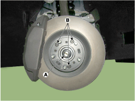
Loosen the drive shaft nut (A), then remove the brake disc by loosening the screw (B-3EA). Tightening torque A: 274.6 ~ 294 N·m (28.0 ~ 30.0 kgf·m, 202.5 ~ 217.1 ft-lbf) B: 4.9 ~ 5.9 N·m
Replace the front hub lock nut with a new one.
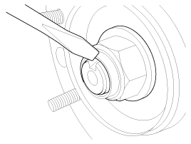
After installing the lock nut, stake the lock nut using a chisel and hammer, as shown in the illustration below.
Staking Depth: 1.5 mm (0.591 in.)
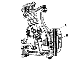
Remove the wheel speed sensor by loosening the wheel speed sensor bracket bolt (A) and the wheel speed sensor mounting bolt (B).
Tightening torque: 6.9 ~ 10.8 N·m
Remove the tie rod end ball joint from the steering knuckle.
Remove the cotter pin.
Remove the castellated nut.
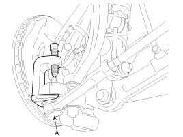
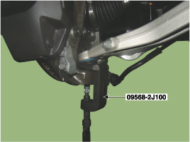
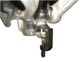
Disconnect the ball joint (A) from the steering knuckle (B) using special service tool (09568-2J100).
Tightening torque: 88.3 ~ 108 N·m
Using special service tool (09568-2J100), remove the pinch bolt from the steering knuckle.
Tightening torque: 88.3 ~ 108 N·m
Loosen the nut, then use special service tool (09568-2J100) to remove the lower arm from the steering knuckle.
Tightening torque: 88.3 ~ 108 N·m
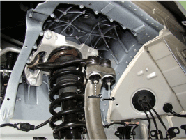
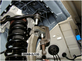
Using SST (09568-2J100), remove the upper arm from the steering knuckle, then separate the steering knuckle assembly.
Tightening Torque: 78.5 ~ 88 N·m
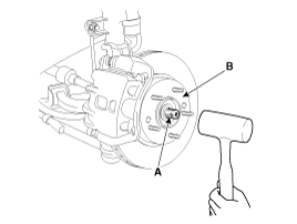
Using a plastic hammer, disconnect the propeller shaft (A) from the axle hub (B).
Loosen the drive belt. [Lambda] (Refer to Engine Mechanical System - "Timing System")
Remove the compressor and secure the other components surrounding the compressor with wire. [Lambda] (Refer to Heating, Ventilation, Air Conditioning - "Compressor")
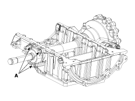
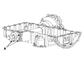
Remove the propeller shaft (LH) by loosening the mounting bolt (A).
Tightening Torque: 53.9 ~ 64 N·m
[LAMBDA][TAU]
When installing the inner propeller shaft, make sure the alignment pin is inserted into the oil hole before tightening the bolts.
Insert a pry bar between the transmission case and the joint case, and separate the drive shaft from the transmission case. [RH]
Install in the reverse order of removal.
Use SST (09581-11000) when installing the brake caliper assembly. (Refer to Brake System - "Rear Disc Brake")
Check the front alignment. (Refer to Suspension System - "Front Wheel Alignment")
?
Test yourself
A quick Hyundai Genesis DH quiz: every answer comes with an explanation and a link to the manual page.