Engine Electrical System
Repair Procedures
In this manual: Engine Electrical System
8steps
~48min
2/5difficulty
Done 0 of 8
Inspection on Vehicle
|

- Check the battery terminals and fuses
- Make sure the battery terminals are not loose or corroded.
- Check the fuses for continuity.
- Inspect the drive belt
- Visually inspect the belt for excessive wear, frayed cords, etc. If any defect is found, replace the drive belt.

- Cracks on the belt ribs are acceptable. If any rib sections are missing from the belt, replace it.
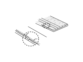
- Visually inspect the belt for excessive wear, frayed cords, etc. If any defect is found, replace the drive belt.
- Adjust the drive belt tension. (Refer to Engine Mechanical System - "Drive Belt")
- Visually inspect the alternator wiring and listen for abnormal noise.
- Make sure the wiring is in good condition.
- Make sure there is no abnormal noise from the alternator with the engine running.
- Check the charge warning light circuit.
- Warm up the engine, then turn it off.
- Turn off all accessories.
- Turn the ignition switch on. Make sure the charge indicator light is on.
- Start the engine. Make sure the light is on. If the light does not go off as specified, perform the charge warning light circuit troubleshooting procedure.
- Alternator Output Wire Voltage Drop Test. This test checks whether the wiring between the alternator "B" terminal and the battery (+) terminal is in good condition using the voltage drop method.
- Preparation
A. Turn the ignition switch to the OFF position. B. Disconnect the output wire from the alternator "B" terminal. Connect the (+) lead of the ammeter to the alternator "B" terminal and the (-) lead of the ammeter to the output wire in series. Connect the (+) lead of the voltmeter to the alternator "B" terminal and the (-) lead of the voltmeter to the battery (+) terminal. 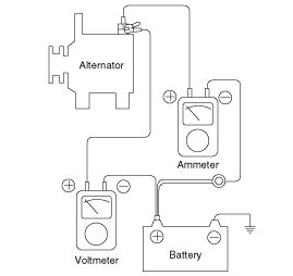
- Test
A. Start the engine. B. Turn on the headlights and blower motor, and adjust engine speed so the ammeter reads 20 A. Then read the voltmeter. - Result
A. The voltmeter may show the standard value. Standard value: 0.2 V max.
B. If the voltmeter reading is higher than expected (above 0.2 V max.), suspect a wiring fault. In this case, check the wiring from the alternator "B" terminal to the battery positive (+) terminal. Check for loose connections, discoloration from wire harness overheating, etc. Repair them before retesting. C. After the test is completed, return engine speed to idle. Turn off the headlights, blower motor and ignition switch.
- Preparation
- Alternator Output Current Test. This test determines whether the alternator produces output current equivalent to normal output current.
- Preparation
A. Before testing, check the following items and correct as necessary. Check the battery installed in the vehicle to make sure it is in good condition. The battery check method is described in the "Battery" section. The battery used for the output current test must be partially discharged. With a fully charged battery, the test may be performed incorrectly due to insufficient load. Check the alternator drive belt tension. The belt tension check method is described in the "Drive Belt Inspection" section. B. Turn the ignition off. C. Disconnect the battery ground cable. D. Disconnect the alternator output wire from the alternator "B" terminal. E. Connect a DC ammeter (0 to 150 A) in series between the "B" terminal and the disconnected output wire. Make sure to connect the negative (-) lead of the ammeter to the disconnected output wire. - Tighten each connection securely because high current will flow. Do not rely on clips.
F. Connect a voltmeter (0 to 20 V) between the "B" terminal and ground. Connect the positive (+) lead to the alternator "B" terminal and the negative (-) lead to a good ground. G. Connect the engine tachometer and connect the battery ground cable. H. Leave the engine hood open. 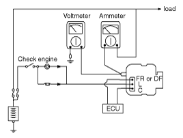
- Test
A. Make sure the voltmeter shows the same value as the battery voltage. If the voltmeter shows 0 V, there is an open circuit in the wire between the alternator "B" terminal and the battery (+) terminal, or a poor ground is suspected. B. Start the engine and turn on the headlights. C. Turn on the high beam headlights and set the heater blower switch to HIGH. Quickly increase the engine speed to 2500 rpm and read the maximum output current value indicated on the ammeter. - After the engine starts, the charging current drops quickly. Therefore, perform the above operation quickly to read the maximum current value correctly.
- Result
A. The ammeter reading should be above the specified limit. If it is below the limit, but the generator output wire is in good condition, remove the generator from the vehicle and inspect it. Limit value: 60% of the voltage standard
- The rated output current is shown on the nameplate attached to the alternator housing.
- The output current value changes depending on the electrical load and the temperature of the alternator itself. Therefore, it may be difficult to obtain the rated current. If so, keep the headlights on to discharge the battery, or use the headlights of another vehicle to increase the electrical load.
- The rated output current cannot be obtained if the generator itself or the ambient temperature is too high. In this case, lower the temperature before retesting.
B. After completing the output current check, reduce the engine speed to idle and turn the ignition switch OFF. C. Disconnect the battery ground cable. D. Remove the ammeter, voltmeter and engine tachometer. E. Connect the generator output wire to the generator "B" terminal. F. Connect the battery ground cable.
- Preparation
- Regulated Voltage Test. The purpose of this test is to check that the electronic voltage regulator controls the voltage correctly.
- Preparation
A. Before testing, check the following items and correct if necessary. Make sure the battery installed in the vehicle is fully charged. For the battery inspection method, refer to the "Battery" section. Check the generator drive belt tension. For the belt tension inspection method, refer to the "Drive Belt Inspection" section. B. Turn the ignition switch to the OFF position. C. Disconnect the battery ground cable. D. Connect a digital voltmeter between the generator "B" terminal and ground. Connect the (+) voltmeter lead to the generator "B" terminal. Connect the (-) lead to a good ground or the battery (-) terminal. E. Disconnect the alternator output wire from the alternator "B" terminal. F. Connect a DC ammeter (0 to 150 A) in series between the "B" terminal and the disconnected output wire. Connect the negative (-) lead of the ammeter to the disconnected output wire. G. Connect the engine tachometer and connect the battery ground cable. - Test
A. Turn the ignition switch ON and check that the voltmeter shows the following value. Voltage: Battery voltage
If the voltmeter reads 0 V, there may be an open circuit or a poor ground connection between the generator "B" terminal and the battery negative (-) terminal.B. Start the engine. Turn off all lights and accessories. C. Run the engine at approximately 2500 rpm and read the voltmeter when the generator output current drops to 10 A or less. - Result
A. If the voltmeter reading does not meet the specified value, the voltage regulator or the generator is faulty. B. After the inspection is complete, reduce the engine speed to idle and turn the ignition switch OFF. C. Disconnect the battery ground cable. D. Remove the voltmeter, the ammeter and the engine tachometer. E. Connect the generator output wire to the generator "B" terminal. F. Connect the battery ground cable.
- Preparation
Test yourself
A quick Hyundai Genesis DH quiz: every answer comes with an explanation and a link to the manual page.
Was this page helpful?