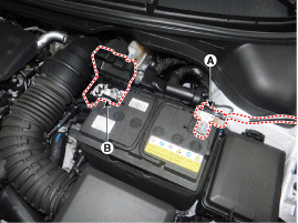
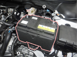
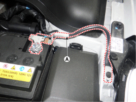
Remove the battery. (Refer to Engine Electrical System - "Battery")
Remove the ECM. (Refer to Engine Control System - "ECM".)
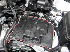
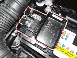
Remove the battery tray (A) after loosening the mounting bolts. Battery tray mounting bolt: 8.8 ~ 13.7 N·m
battery holder
REMEDY
To install, perform the removal procedure in reverse order.
ITEM
Battery Charge
In general, the vehicle battery charging system has three forms.
Constant current charging: the battery voltage gradually increases while charging with a constant current charger. If the charging time and current are not correct, the battery may be overcharged. Therefore, stop charging after confirming that charging is complete.
Slow charge: charging the battery for a long time with a low current
Quick charge: charging the battery for a short time with a high current
Constant voltage charging: the battery charging current gradually decreases while charging with a constant voltage regulated charger.
Inspection
Battery Condition and Voltage: Check the battery condition and voltage using a battery tester. BATTERY TERMINAL
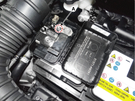
Move the battery terminal clamps back and forth (A) to check if they are loose or corroded. Clean all corroded terminals.If the battery positive (+) terminal connection is too loose, disconnect the ground (GND) cable before removing or tightening the positive connection to avoid injury.
If the battery clamp on the positive (+) battery terminal is not properly positioned:
Turn the ignition switch to the OFF position and disconnect the negative (-) battery terminal.
Tighten the battery clamp (A) on the positive (+) battery terminal. Positive (+) battery terminal: 7.8 – 9.8 N·m
If the battery clamp on the negative (-) battery terminal is not properly positioned:
Tighten the battery clamp (A) on the negative (-) battery terminal. Negative (-) battery terminal: 4.0 – 6 N·m
Turn off all electrical devices, then turn off the ignition switch.
Close all doors except the hood, then lock all doors.
Disconnect the hood switch connector.
Close the trunk.
Close the doors or remove the door switches.
Wait several minutes for the vehicle's electrical systems to go to sleep.
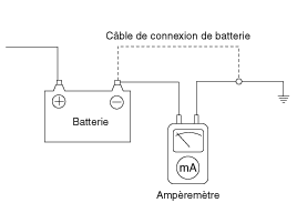
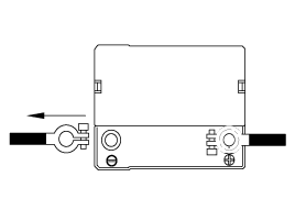
Connect an ammeter in series between the negative (-) battery terminal and the ground cable, then slowly disconnect the clamp from the negative (-) battery terminal.
Read the current value on the ammeter.
If the dark current is higher than the limit value, check for an abnormal circuit by removing the fuses one at a time and monitoring the dark current.
Reconnect only the suspected parasitic dark current fuse and locate the faulty unit by disconnecting components connected to the circuit until the dark current drops below the limit value.
Limit value (after 10-20 min.): Less than 50 mA
Turn off all electrical devices, then turn off the ignition switch.
Close all doors except the hood, then lock all doors.
Disconnect the hood switch connector.
Close the trunk.
Close the doors or remove the door switches.
Wait several minutes for the vehicle's electrical systems to go to sleep.
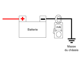
Install the clamp-on ammeter on the negative (-) battery cable.
Read the current value on the ammeter.
If the dark current is higher than the limit value, check for an abnormal circuit by removing the fuses one at a time and monitoring the dark current.
Reconnect only the suspected parasitic dark current fuse and locate the faulty unit by disconnecting components connected to the circuit until the dark current drops below the limit value.
Limit value (after 10-20 min.): Less than 50 mA
Battery Charge: Check whether the battery is damaged or deformed. If serious damage, deformation, or leakage is found, replace the battery. Vehicle Dark Current Check [Using an Ammeter] [Using a Clamp-Type Ammeter]
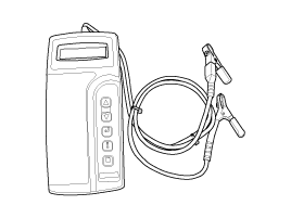
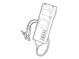
MICRO 570 ANALYZER
Using the Micro 570 analyzer, charging and starting systems, including the battery, starter, and alternator, can be tested.
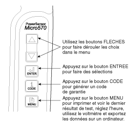
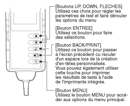
KEYPAD: The Micro 570 keypad buttons perform the following functions:BATTERY TEST PROCEDURE
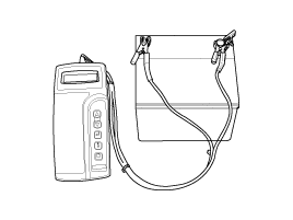
Connect the tester to the battery.
Connect the red clamp to the positive (+) battery terminal.
Connect the black clamp to the negative (-) battery terminal.
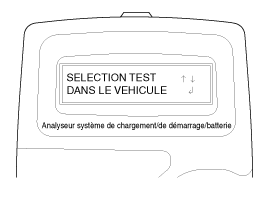
The tester will ask whether the connected battery is "IN VEHICLE" or "OUT OF VEHICLE". Select using the arrow keys, then press "ENTER".
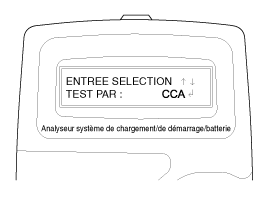
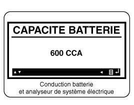
Select CCA and press the ENTER key.
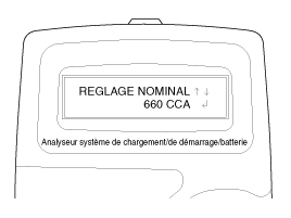
Using the up and down keys, set the CCA value shown on the screen to the CCA value shown on the battery label, then press "ENTER".
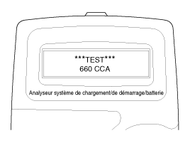
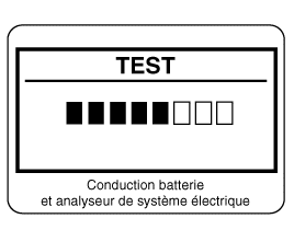
The tester will perform the battery test.
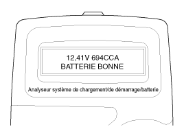
The tester displays the battery test results, including voltage and battery rating. Refer to the following table and take the appropriate action recommended by the Micro 570.BATTERY TEST RESULTS
PRINT RESULT
REMEDY
Battery is good
No action required.
GOOD - RECHARGE
The battery is in good condition. Charge the battery before use.
When charging, follow the instructions below before the battery test; otherwise the test result may be inaccurate. (See "Charge and Retest After Charging the Battery" below.)
Charge and retest
Battery incorrectly charged
Charge and retest the battery.
When charging, follow the instructions below before the battery test; otherwise the test result may be inaccurate. (See "Charge and Retest After Charging the Battery" below.)
Replace the battery
Replace the battery and retest the charging system.
An incorrect connection between the battery and the vehicle cables may cause the message "REPLACE BATTERY" to appear. Retest the battery after disconnecting the cables and connecting the tester directly to the battery terminal, immediately before replacing the battery.
Faulty cell - replace
Charge and retest the battery.
If the Micro 570 displays the message "REPLACE BATTERY", replace the battery and retest the charging system.
[Charge and retest after charging the battery] Charge the battery: Set the charger to "Automatic mode" (a mode in which the charging current decreases as the battery charges) and charge the battery until the charging current drops close to zero or the charger signals with a beep that charging is complete. (Minimum recommended charging time: more than 3 hours in Automatic mode as explained above)
If the battery is not fully charged, the surface charge of the battery is high when the amount of cold cranking amps (CCA) available from the battery is reduced. If the battery is tested in this condition, the tester may incorrectly evaluate that battery sulfation has occurred, because the current level in the battery is too low compared to the battery voltage. *Surface charge: when the battery is charged, the temperature and electrolyte level rise and the chemical reaction becomes active, causing an excessive increase in battery voltage. It is known that approximately 24 hours are required for full recovery from this elevated surface charge.
Battery test after charging: Do not test the battery immediately after charging. Test the battery once the surface charge has dissipated, as described in the following procedure.
After completing the battery charging, install the battery in the vehicle.
Turn the ignition on, turn on the low beam headlights, and wait for 5 minutes. (5-minute discharge.)
Turn all headlights to the ALL ON position and wait 5 minutes.
Disconnect the positive (+) and negative (-) battery cables and test the battery.
STARTER TEST PROCEDURE
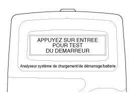
After the battery test, immediately press the ENTER key to perform the starter test.
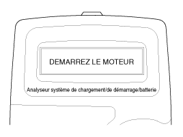
Start the engine.
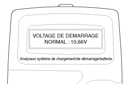
The starting voltage and starter test results are shown on the screen. Refer to the following table and take the appropriate action. Recommended: Micro 570.STARTER TEST RESULTS
PRINT RESULT
REMEDY
Normal Starting Voltage
The system indicates that the starter is normal.
Low Starting Voltage
Starting voltage is below the normal value.
Check the starter
Charge the battery.
The battery charge level is too low for testing.
Charge the battery and repeat the test.
Replace the battery
Replace the battery.
If the vehicle does not start while the battery shows "GOOD BATTERY", check for an open circuit in the wiring, battery cable connections, and the starter, and repair or replace as necessary.
If the engine still cannot be started, check the fuel system.
CHARGING SYSTEM TEST PROCEDURE
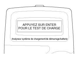
Press the ENTER key to start the charging system test.
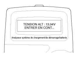
The tester displays the actual alternator voltage. Press ENTER to continue.
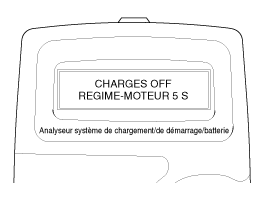
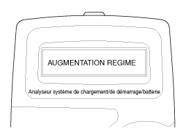
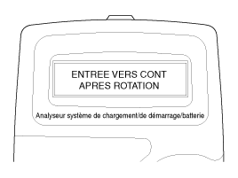
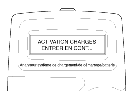
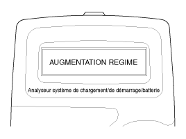
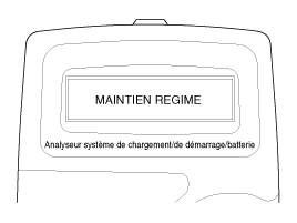
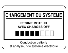
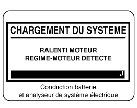
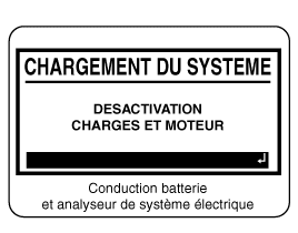
Turn off all electrical loads and crank the engine for 5 seconds by depressing the accelerator pedal. (Follow the on-screen instructions.)
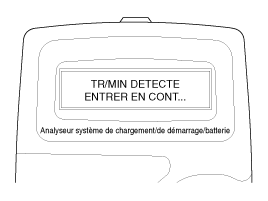
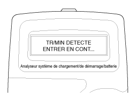
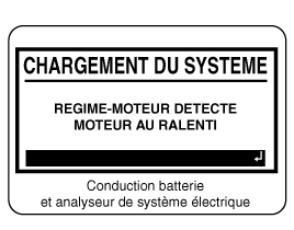
A message indicating that the engine speed has been detected is displayed on the screen. Press ENTER to continue.
If the engine speed is not detected, press ENTER after cranking the engine.
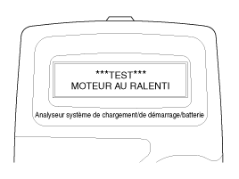
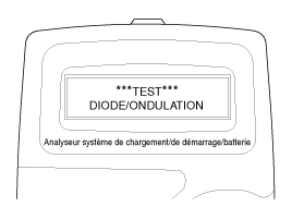
The tester performs the no-load system test.
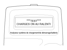
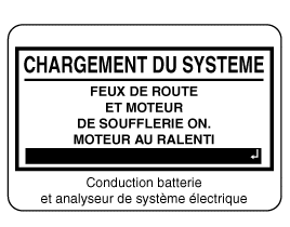
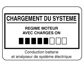
Start the engine with the electrical loads turned on.
The tester performs the loaded system test.
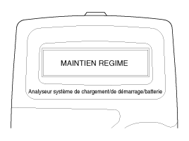
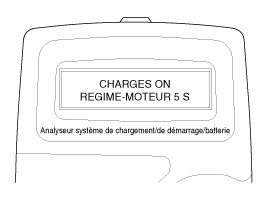
Run the engine for 5 seconds while depressing the accelerator pedal. (Follow the on-screen instructions.)
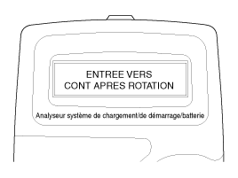
A message indicating that the engine speed has been detected is displayed on the screen. Press ENTER to continue.
If the engine speed is not detected, press ENTER after cranking the engine.
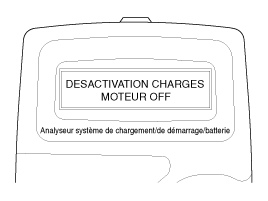
Turn off the electrical loads (air conditioning, lights, audio system, etc.). Turn off the engine.
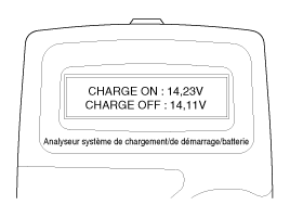
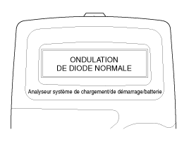
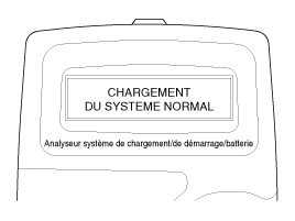
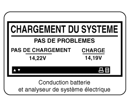
The charging voltage and charging test results are displayed on the screen. Turn off the engine and disconnect the tester leads from the battery. Refer to the following table and take the appropriate action. Recommended: Micro 570.CHARGING SYSTEM TEST RESULTS
PRINT RESULT
REMEDY
SYSTEM LOAD NORMAL / DIODE RIPPLE NORMAL
The charging system is functioning normally.
No Load Voltage
The alternator is not supplying charging current to the battery.
Check the belts and the connection between the alternator and the battery, and replace the belt, cable, or alternator as necessary.
Low Charging Voltage
The alternator is not supplying charging current to the battery, and there is not sufficient electrical load on the system.
Check the belts and the alternator, and replace if necessary.
High Charging Voltage
The voltage from the alternator to the battery is above the permissible limit. Normal during voltage regulation.
Check the connections and grounds, and replace the regulator if necessary.
Check the electrolyte level in the battery.
Excessive ripple detected
One or more alternator diodes are not functioning properly.
Check the alternator assembly and belts, and replace if necessary.
MDX-670P Analyzer: The MDX-670P Battery and Electrical System Conductance Analyzer tests batteries as well as vehicle charging and starting systems. It displays test results within seconds and has a built-in printer that provides a copy of the results.
Connect the red clamp to the positive (+) terminal and the black clamp to the negative (-) terminal.
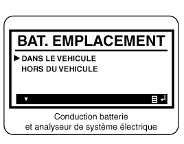
Scroll and select IN VEHICLE or OUT OF VEHICLE for a battery not connected to the vehicle.
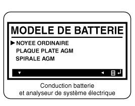
Scroll and select NORMAL LOAD, FLAT PLATE AGM, or AGM SPIRAL, as applicable.
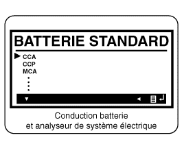
Scroll and select the battery rating system.
CCA: Cold Cranking Amps, as specified by SAE, is the most common rating for batteries, starting at 0°F (-17.8°C).
EN: European standard
SAE: Society of Automotive Engineers, the American standard
Use the UP and DOWN keys to set the selected value to the value shown on the battery label.
Press ENTER to start the test.
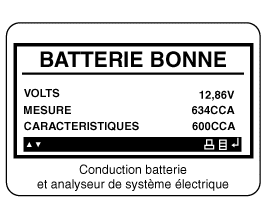
After a few seconds, the tester displays the battery condition and measured voltage. The tester also shows the battery capacity and power units.BATTERY TEST RESULTS
PRINT RESULT
REMEDY
Battery is good
No action required.
GOOD - RECHARGE
The battery is in good condition. Charge the battery before use.
When charging, follow the instructions below before the battery test; otherwise the test result may be inaccurate. (See "Charge and Retest After Charging the Battery" below.)
Charge and retest
Battery incorrectly charged
Charge and retest the battery.
When charging, follow the instructions below before the battery test; otherwise the test result may be inaccurate. (See "Charge and Retest After Charging the Battery" below.)
Replace the battery
Replace the battery and retest the charging system.
An incorrect connection between the battery and the vehicle cables may cause the message "REPLACE BATTERY" to appear. Retest the battery after disconnecting the cables and connecting the tester directly to the battery terminal, immediately before replacing the battery.
BAD CELL - REPLACE
Charge and retest the battery.
If the message "REPLACE BATTERY" appears on the MDX-670P analyzer, replace the battery and retest the charging system.
[Charge the battery and repeat the test after charging] Battery Charging. Set the charger to "Automatic Mode" (a mode in which the charging current decreases as the battery charges) and charge the battery until the charging current drops to near zero or the charger signals with an audible tone that charging is complete. (Recommended minimum charging time: more than 3 hours in the automatic mode described above.)
If the battery is not fully charged, the surface charge voltage of the battery is high when the amount of cold cranking current (CCA) in the battery is low. If the battery is tested in this condition, the tester may incorrectly judge that the battery has sulfation, because the current level in the battery is too low compared to the battery voltage. * Surface charge: When the battery is charged, the electrolyte temperature rises and the chemical reaction becomes active, causing the battery voltage to rise excessively. It is known that about one day is required for complete recovery from this elevated surface charge.
Battery test after charging: Do not test the battery immediately after charging. Test the battery once the surface charge has dissipated, as described in the following procedure.
After completing the battery charging, install the battery in the vehicle.
Turn the ignition on, turn on the low beam headlights, and wait for 5 minutes. (5-minute discharge.)
Turn all headlights to the ALL ON position and wait 5 minutes.
Disconnect the positive (+) and negative (-) battery cables and test the battery.
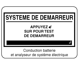
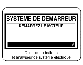
Press the ENTER button to start the starter test.
Start the engine when prompted.
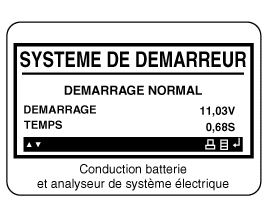
The tester displays the starter system status, ignition voltage, and ignition time in milliseconds.STARTER TEST RESULTS
PRINT RESULT
REMEDY
Normal Starting Voltage
The system indicates that the starter is normal.
Low Starting Voltage
Starting voltage is below the normal value.
Check the starter
Charge the battery.
The battery charge level is too low for testing.
Charge the battery and repeat the test.
Replace the battery
Replace the battery.
If the vehicle does not start while the battery shows "GOOD BATTERY", check for an open circuit in the wiring, battery cable connections, and the starter, and repair or replace as necessary.
If the engine starts, inspect the fuel system.
Step 3: Charging System Test
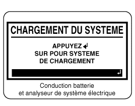
Press the ENTER button to start the load test.
Start the engine with no load. (Follow the prompts on the screen.)
The screen displays a message that the engine speed has been detected. Set the engine to idle.
Turn on the electrical loads (air conditioner, lights, audio system, etc.). Press ENTER to continue.
Turn on the electrical loads (air conditioner, lights, audio system, etc.). Press ENTER to continue.
The screen displays a message that the engine speed has been detected. Set the engine to idle.
Stop the load and the engine.
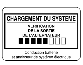
The charging system status is displayed at the end of the procedure.
PRINT RESULT
REMEDY
NO PROBLEM
The system shows normal generator output.
NO OUTPUT
No generator output detected.
Check all connections to and from the generator, especially the battery connection. If a connection is loose or heavily corroded, clean or replace the cable and repeat the test.
If the belts and connections are in good condition, replace the generator. (Older vehicles use external voltage regulators, which may require replacement of the voltage regulator as a unit.)
Low Output
The alternator is not supplying charging current to the battery, and there is not sufficient electrical load on the system.
Check the belts and the alternator, and replace if necessary.
HIGH OUTPUT
The voltage from the alternator to the battery is above the permissible limit. Normal during voltage regulation.
Check the connections and grounds, and replace the regulator if necessary.
Check the electrolyte level in the battery.
EXCESSIVE RIPPLE
The voltage from the alternator to the battery is above the permissible limit. Normal during voltage regulation.
Check the alternator assembly and belts, and replace if necessary.
Charge the battery.
Starter voltage is low, the battery is discharged. Fully charge the battery and repeat the starter system test.
Replace the battery
The battery must be replaced before the system can be tested.
Press the BACK/PRINT button to save the test results, or MENU to return to the options menu.
CLEANING
Make sure the ignition switch and all accessories are off.
Disconnect the battery cables (negative terminal first).
Remove the battery from the vehicle.
Make sure the battery holder is not damaged by electrolyte loss. If it is, clean the affected area with a solution of clean warm water and sodium bicarbonate (baking soda). Scrub the area with a stiff brush and wipe it with a cloth dampened with the baking soda solution.
Clean the top of the battery with the solution described above.
Check the top of the battery case and its cover for cracks. If there are cracks, replace the battery.
Clean the terminals with a suitable tool.
Clean the inside surface of the connector clamps with a suitable tool. Replace worn or damaged cables and broken connector clamps.
Install the battery in the vehicle.
Connect the terminals to the battery terminals, making sure the tops of the terminals and posts are flush.
Tighten the flange nuts to the specified torque.
Coat all connections with petroleum jelly after tightening.
?
Test yourself
A quick Hyundai i20 quiz: every answer comes with an explanation and a link to the manual page.