Remove the engine assembly from the vehicle. (See Engine and Transaxle - Engine and Transaxle)
Remove the transaxle assembly from the engine assembly. (See Manual Transaxle System - Manual Transaxle)
Remove the flywheel. (See Cylinder Block Assembly - Flywheel)
Remove the rear oil seal. (See Cylinder Block Assembly - Rear Oil Seal)
Install the engine on an engine stand for disassembly.
Remove the cylinder head cover. (Refer to Cylinder Head - "Cylinder Head Cover")
Remove the thermostat housing. Refer to Cooling System - "Thermostat".
Remove the timing chain. (Refer to Valve Timing System - Timing Chain)
Remove the intake manifold. (Refer to Exhaust and Intake System - "Intake Manifold")
Remove the exhaust manifold. (Refer to Intake and Exhaust System - "Turbocharger and Exhaust Manifold")
Remove the cylinder head. (See Cylinder Head - Cylinder Head)
Remove the oil pan and oil filter. (See Lubrication System - Oil Pan)
Remove the ladder frame. (See Cylinder Block - Cylinder Block)
Remove the piston and connecting rod assembly. (Refer to Cylinder Block Assembly - Piston and Connecting Rod.)
Check the oil clearance of the main bearing.
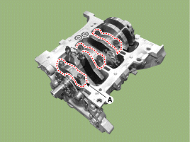
Remove the main bearing caps (A).
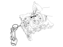
Check the crankshaft end play.
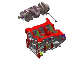
Lift the crankshaft (A) and carefully remove it from the engine so as not to damage the dowels.
Inspection
Check the oil clearance of the crankshaft main bearings.
To check the oil clearance between the main bearing and journal, remove the main bearings.
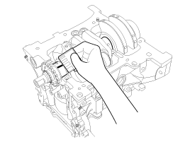
Clean each main journal and bearing half with a clean cloth.
Place a strip of Plastigage on each main journal.
Install the bearings and bolts as follows, then tighten to the specified torque.
Tightening torque: 17.7 - 22 N·m + 103 - 105°
Remove the cap and bearing again, then measure the widest part of the Plastigage.
Standard oil clearance: 0.006 - 0.024 mm (0.0002 - 0.0009 in.)
If the Plastigage measurement is too large or too narrow, remove the upper bearing half, install a new bearing, select the bearing with the same color mark (select the color as shown in the following table), and check the clearance again.
If the Plastigage measurement is still incorrect, try a larger or smaller bearing and check the clearance again.
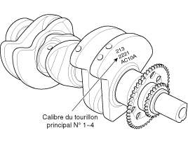
[The location of the bore marks for the crankshaft journals is on the cylinder block. The letters are stamped on the front face of the block as size marks for each of the 5 main journal bores. Use them, together with the numbers or stripes stamped on the crankshaft (main bearing size marks), to select the correct bearings.The crankshaft journal bore identification is located on the cylinder block.
Rating
Mark
The inner diameter of the crankshaft journal bore is located in the cylinder block.
B
B
52.000 - 52.006 mm (2.0472 - 2.0475 in.)
B
B
52.006 - 52.012 mm (2.0475 - 2.0477 in.)
AGAINST
AGAINST
52.012 - 52.018 mm (2.0477 - 2.0480 in.)
Location of the mark on the crankshaft main journalCrankshaft main journal identification
GRADE
Mark
Outer diameter of the crankshaft main journal
I
1
47.954 - 47.960 mm (1.8880 - 1.8882 in.)
II
2
47.948 - 47.954 mm (1.8877 - 1.8880 in.)
III
3
47.942 - 47.948 mm (1.8875 - 1.8877 in.)
Location of the crankshaft main bearing marksCrankshaft main bearing identification
Mark
Color
Thickness of the crankshaft main bearing
B
BLUE
2.026 - 2.029 mm (0.0797 - 0.0798 in.)
B
BLACK
2.023 - 2.026 mm (0.0796 - 0.0797 in.)
AGAINST
NONE
2.020 - 2.023 mm (0.0795 - 0.0796 in.)
D
GREEN
2.017 - 2.020 mm (0.0794 - 0.0795 in.)
E
YELLOW
2.014 - 2.017 mm (0.0793 - 0.0794 in.)
Select the bearing from the selection table. Crankshaft main bearing selection table
crankshaft main bearing
The bore mark on the crankshaft journal is located on the cylinder block.
has)
B (B)
cc)
Crankshaft main journal mark
I (1)
E (Yellow)
D (Green)
C (None)
II (2)
D (Green)
C (None)
B (Black)
III (3)
C (None)
B (Black)
Blue)
Check the crankshaft end play. Using a dial indicator, measure the end play by prying the crankshaft forward and backward with a screwdriver.
Standard crankshaft end play: 0.07 - 0.25 mm (0.0028 - 0.0098 in.)
If the end play exceeds the maximum value, replace the thrust bearings as a set. Thrust bearing thickness: 1.925 - 1.965 mm (0.0757 - 0.0774 in.). Crankshaft end play: 0.07 - 0.25 mm (0.0028 - 0.0098 in.)
Check the main journals and main bearing journals of the crankshaft. Using a micrometer, measure the diameter of each main journal and bearing journal. Main journal diameter: 42.942 - 42.960 mm (1.6906 - 1.6913 in.). Bearing journal diameter: 38.954 - 38.972 mm (1.5336 - 1.5343 in.)
Installation
Install the crankshaft main bearings.
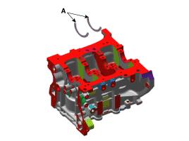
Align the bearing tab with the tab groove of the cylinder block and press in the 4 upper bearings (A).
Install the two thrust bearings (A) on either side of the No. 2 bearing position, with the oil grooves facing outward.
Install the crankshaft (A) on the cylinder block.
Install the main bearing cap (A).
Install and tighten the 8 main bearing cap bolts in several passes, in the specified sequence.
Tightening torque: 17.7 - 22 N·m + 103 - 105°
Make sure the crankshaft rotates freely.
Check the crankshaft end play.
Install the remaining parts in the reverse order of removal.
?
Test yourself
A quick Hyundai i20 quiz: every answer comes with an explanation and a link to the manual page.