Remove the engine assembly from the vehicle. (See Engine and Transaxle - Engine and Transaxle)
Remove the transaxle assembly from the engine assembly. (See Manual Transaxle System - Manual Transaxle)
Remove the flywheel. (See Cylinder Block Assembly - Flywheel)
Remove the rear oil seal. (See Cylinder Block Assembly - Rear Oil Seal)
Install the engine on an engine stand for disassembly.
Remove the cylinder head cover. (Refer to Cylinder Head - "Cylinder Head Cover")
Remove the thermostat housing. Refer to Cooling System - "Thermostat".
Remove the timing chain. (Refer to Valve Timing System - Timing Chain)
Remove the intake manifold. (Refer to Exhaust and Intake System - "Intake Manifold")
Remove the exhaust manifold. (Refer to Intake and Exhaust System - "Turbocharger and Exhaust Manifold")
Remove the cylinder head. (See Cylinder Head - Cylinder Head)
Remove the oil pan and oil filter. (See Lubrication System - Oil Pan)
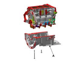
Remove the ladder frame (A). Insert a stainless steel blade (09215-3C000) between the cylinder block and the ladder frame, and cut the sealant bead. Then remove the ladder frame.
Inspect the connecting rod side clearance. (Refer to Cylinder Block Assembly - "Piston and Connecting Rod".)
Inspect the connecting rod bearing cap oil clearance. (Refer to Cylinder Block Assembly - "Piston and Connecting Rod".)
Remove the piston and connecting rod assembly. (Refer to Cylinder Block Assembly - Piston and Connecting Rod.)
Inspect the main bearing oil clearance. (Refer to Cylinder Block Assembly - "Crankshaft".)
Inspect the crankshaft end play. (Refer to Cylinder Block Assembly - "Crankshaft".)
Remove the crankshaft. (Refer to Cylinder Block Assembly - "Crankshaft".)
Remove the water jacket spacer. (Refer to Cylinder Block - "Water Jacket Spacer".)
Remove the oil jet (A).
Inspection
Remove the sealing material. Using a scraper, remove the sealant from the surface of the upper part of the cylinder block.
Clean the cylinder block. Using a brush and solvent, thoroughly clean the cylinder block.
Inspect the flatness of the cylinder block upper surface. Using a precision straightedge and feeler gauge, measure the distortion of the cylinder head gasket surface. Cylinder block gasket surface flatness Standard: Less than 0.05 mm (0.002 in) Less than 0.02 mm (0.0008 in)/100 x 100 (3.937 x 3.937 in)
Inspect the cylinder bore. Make sure the cylinder is not scratched vertically. If deep scratches are found, replace the cylinder block.
Inspect the cylinder bore diameter. Using a cylinder bore gauge, measure the bore diameter at the thrust and axial directions.
Standard diameter: 71.00~71.03 mm (2.7952~2.7964 in)
Check the cylinder bore size code on the cylinder block.Cylinder Block Specifications
GRADE
Mark
Inside diameter
B
B
71.00~71.01 mm (2.79528~2.79567 in)
B
B
71.01~71.02 mm (2.79567~2.79606 in)
AGAINST
AGAINST
71.02~71.03 mm (2.79606~2.79646 in)
Check the piston size code on the piston top surface.Piston Outer Diameter
GRADE
Mark
Inside diameter
B
B
70.965~70.975 mm (2.79390~2.79429 in)
B
B
70.975~70.985 mm (2.79429~2.79469 in)
AGAINST
AGAINST
70.985~70.995 mm (2.79469~2.79508 in)
Select a piston that matches the cylinder bore code.
Clearance: 0.025 ~ 0.045 mm (0.00098 ~ 0.00177 in)
Installation
Install the oil jet (A).
Tightening torque: 8.8 - 12.7 N·m
Install the water jacket spacer. (Refer to Cylinder Block - "Water Jacket Spacer".)
Install the crankshaft. (Refer to Cylinder Block Assembly - "Crankshaft".)
Inspect the crankshaft end play. (Refer to Cylinder Block Assembly - "Crankshaft".)
Inspect the main bearing oil clearance. (Refer to Cylinder Block Assembly - "Crankshaft".)
Install the piston and connecting rod assembly. (Refer to Cylinder Block Assembly - "Piston and Connecting Rod".)
Inspect the connecting rod bearing cap oil clearance. (Refer to Cylinder Block Assembly - "Piston and Connecting Rod".)
Inspect the connecting rod side clearance. (Refer to Cylinder Block Assembly - "Piston and Connecting Rod".)
Install the ladder frame.
Using a scraper, remove the old sealant.
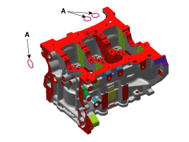
Install the O-ring (A) on the cylinder block.
Apply liquid sealant to the ladder frame mating surface before installing the ladder frame. Assemble the parts within 5 minutes after applying the sealant.
Bead width: 2.5 ~ 3.5 mm (0.1 ~ 0.14 in)
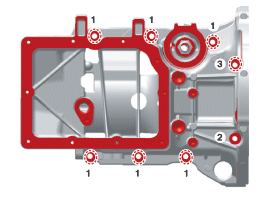
Install and tighten the frame bolts evenly, in several passes.
Tightening torque: 19.6 - 24 N·m
Install the remaining parts in the reverse order of removal.
?
Test yourself
A quick Hyundai i20 quiz: every answer comes with an explanation and a link to the manual page.