In this manual: Advanced Driver Assistance System (ADAS)
28steps
~183min
5/5difficulty
3special tools
Tightening torque found on this page
Done 0 of 28
Specifications
Specification
Item
Specification
Supply voltage (V)
12
Operating Voltage (V)
9 - 16
Description and Operation
Description
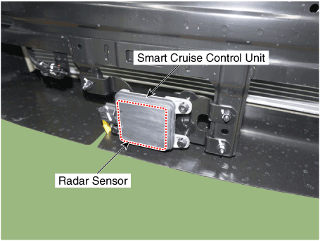
The Smart Cruise Control unit is installed in the front right side of the chassis. The radar sensor is built into the front of the unit. This sensor detects vehicles and objects in front of the vehicle. The radar sensor can detect up to 32 objects ahead of the vehicle. A warning is activated when the vehicle deviates from the horizontal and vertical alignment reference points during operation. This sensor communicates with the instrument panel, warning buzzer, Smart Cruise Control switch, Electronic Stability Program (ESP), ECM, and TCM via the CAN bus. The sensor monitors vehicle speed via CAN communication between the Electronic Stability Program (ESP) system and the ECM and TCM.
Repair Procedures
Inspection
Inspection Procedure for Forward Collision-Avoidance Assist System and Smart Cruise Control System Malfunction
Check the bumper for signs of collision damage (visually inspect the vehicle and check the bumper replacement history). → If the vehicle has been in a collision, there is a high possibility that the FCA radar is out of its default original position.
Check the radar sensor cover on the bumper for contamination. → If contaminated, there is a high possibility that the FCA system will be disabled during operation due to foreign substances.
After starting the engine, check the FCA warning lamp and DTCs. (Refer to the Diagnostic Trouble Code Troubleshooting Manual.)
Removal
Turn the ignition switch OFF and disconnect the negative (-) battery cable.
Remove the front bumper. (Refer to Body - "Front Bumper")
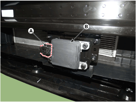
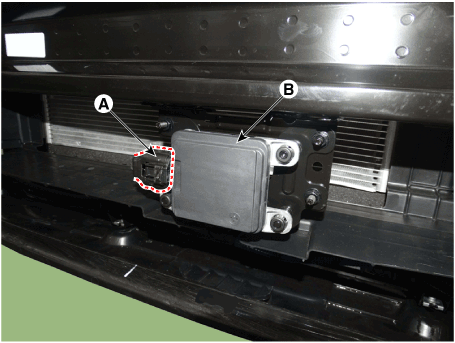
Disconnect the front radar connector (A).
Loosen the mounting nuts and remove the front radar (B).
Front radar nuts: 9.8–11.8 N·m
Installation
Park the vehicle on a level surface.
Remove any heavy luggage from the seats or cargo area.
Inflate all tires to the specified pressure.
Check the wheel alignment.
Make sure the front surface of the front radar is clean.
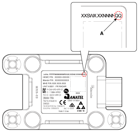
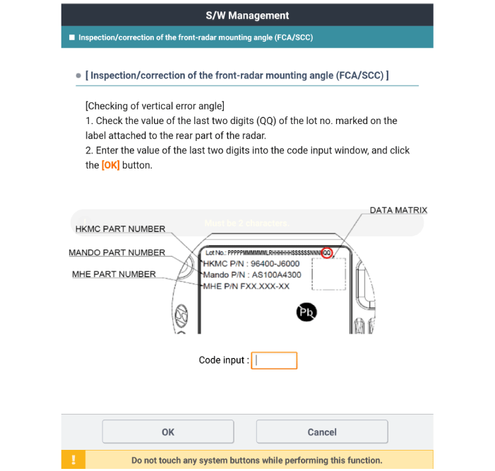
Check the last 2 digits of the Lot No. There is no (A) on the label at the rear before installing the front radar.
Lot No. (A) value – vertical deviation angle of the inner side of the front radar.
Install the front radar (B) by tightening the nuts, and connect the front radar connector (A).
Front radar nuts: 9.5–10.5 N·m
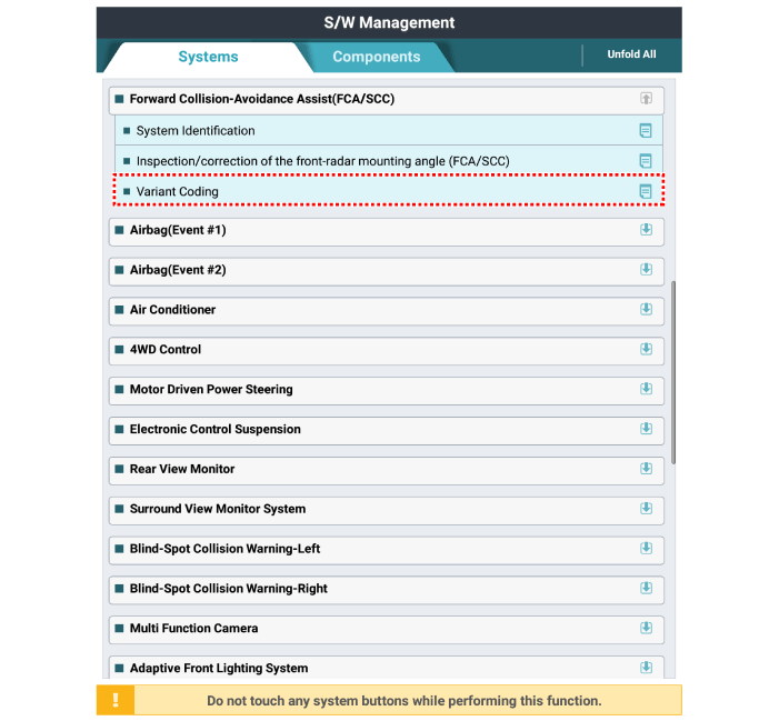
If the front radar has been replaced with a new one, perform the variant coding procedure using the diagnostic tool.
Check and adjust the front radar alignment angle.
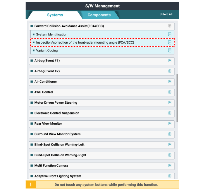
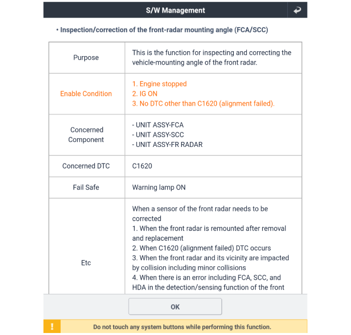
Perform the "Front Radar Mounting Check/Adjustment" procedure with the diagnostic tool.
Enter the 2-digit value in the code input field, then click "OK".
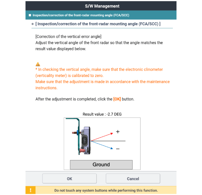
Check the vertical angle, which compensates for the error in the diagnostic tool.
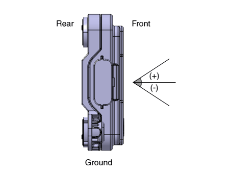
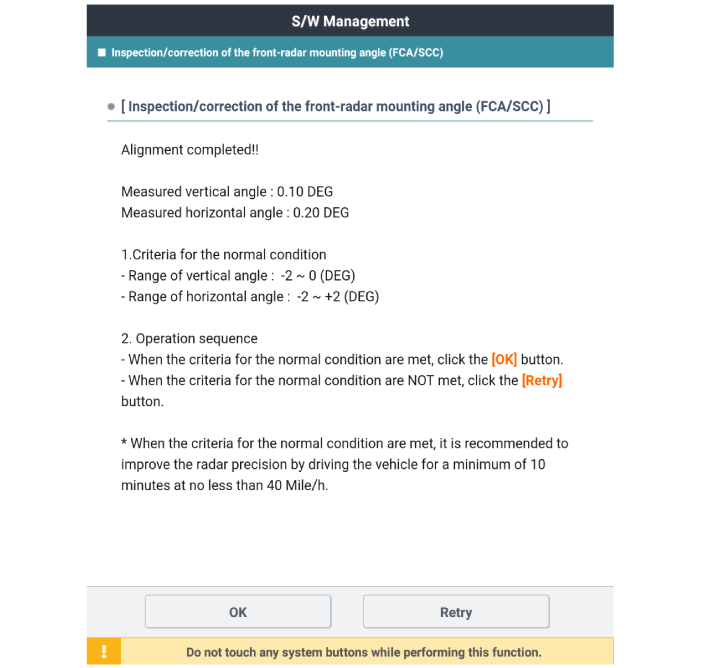
The result is the final vertical target angle, which is the compensated internal error. The vertical installation angle criteria is -1°.
Check the front radar vertical angle using a vertical protractor (inclinometer).
Be sure to perform zero setting before using the vertical protractor (perform this procedure periodically).
Be careful of the +/- readings when finding the true vertical with the vertical protractor.
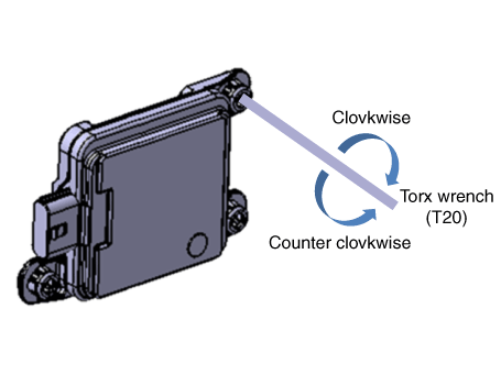
Adjust the "target vertical angle" by turning the front radar adjusting screw.
Clockwise rotation: adjusts the angle (+)
Counterclockwise rotation: adjusts the angle (-)
There is a risk of deforming the bracket if the adjusting screw is turned with excessive force.
After adjustment, be sure to recheck with the vertical protractor that the vertical angle is correct.
Number of turns of the adjusting screw
Correction angle
Clockwise
Counterclockwise
0,5
+ 0,5°
- 0,5°
1
+ 1,0°
- 1,0°
1,5
+ 1,5°
- 1,5°
2
+ 2,0°
- 2,0°
2,5
+ 2,5°
- 2,5°
3
+ 3,0°
- 3,0°
3,5
+ 3,5°
- 3,5°
4
+ 4,0°
- 4,0°
4,5
+ 4,5°
- 4,5°
5
+ 5,0°
- 5,0°
Install the front bumper assembly. (Refer to Body - "Front Bumper Assembly")
Perform the front radar check/adjustment procedure using the SST. (Refer to Intelligent Cruise Control (Stop & Go) (SCC) Unit-Radar - "Adjustment")
Adjustment
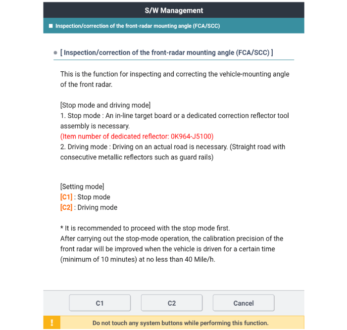
Front Radar Mounting Angle Inspection/Adjustment Overview: The front radar detects the control object ahead and recognizes the distance to it by comparing speed and other factors. For these reasons, the mounting direction must be collinear with the vehicle. Therefore, mounting angle inspection and adjustment must be performed if the front radar has been removed and reinstalled due to an accident, or if a new front radar is installed. The accuracy of the front radar cannot be guaranteed if inspection and adjustment have not been performed in the above situations. Front radar inspection/adjustment must be performed either in Stationary mode (C1) or Driving mode (C2) using the GDS Perform procedure with the Special Service Tool (SST) reflector for Stationary mode (C1).
After stop-mode operation, accuracy will improve if the vehicle has been driven for more than 10 minutes. (Drive on a straight road with metal reflectors.)
Perform adjustment while driving on an actual road (drive on a road with many metal fixed reflectors, such as guardrails) for driving mode. (C2)
Cases in which front radar alignment angle check/adjustment is required.
Front radar has been replaced.
Front radar has been removed and reinstalled.
Line up failed DTC has occurred.
Front radar detection and recognition function malfunction
Fails to detect a preceding vehicle during operation.
Frequently detects lane error.
Frequently detects an error even when no object is ahead.
How to Inspect/Adjust Front Radar Mounting Angle - Stationary Mode
Preparation before front radar alignment:
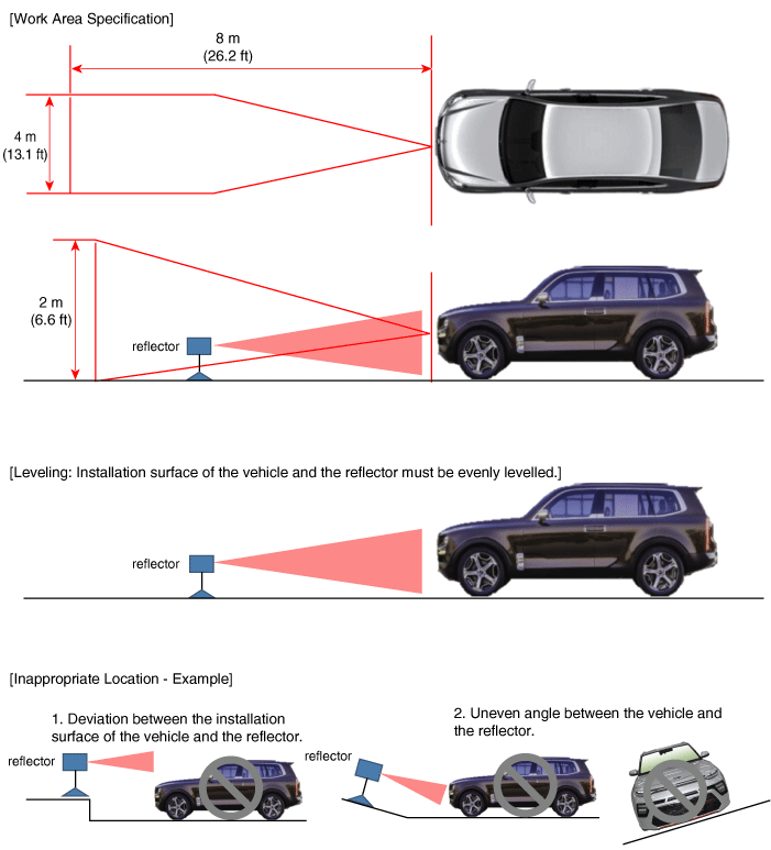
Park the vehicle on a level surface.
Remove any heavy luggage from the seats or cargo area.
Inflate all tires to the specified pressure.
Check the wheel alignment.
Make sure the front surface of the front radar is clean.
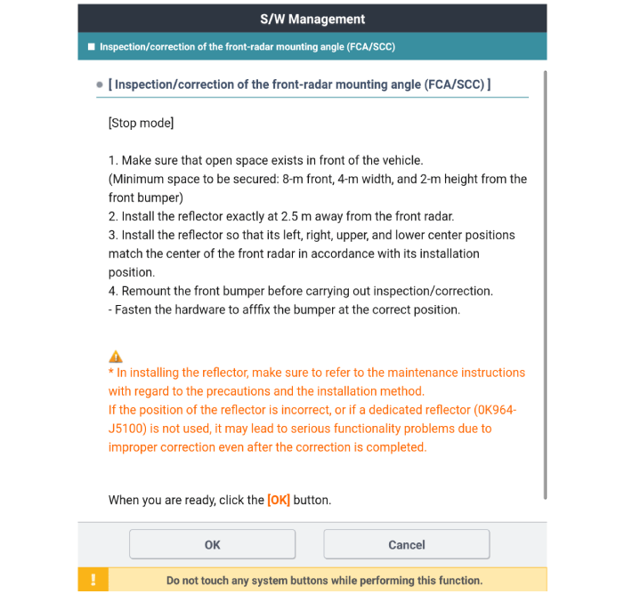
Perform in an area with a minimum clearance of 8 m (26.2 ft) in front, 4 m (13.1 ft) to the sides, and 2 m (6.6 ft) above the vehicle.
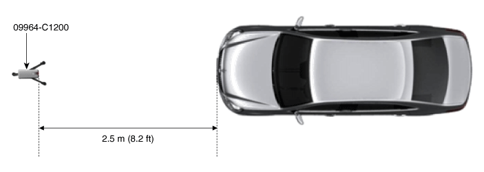
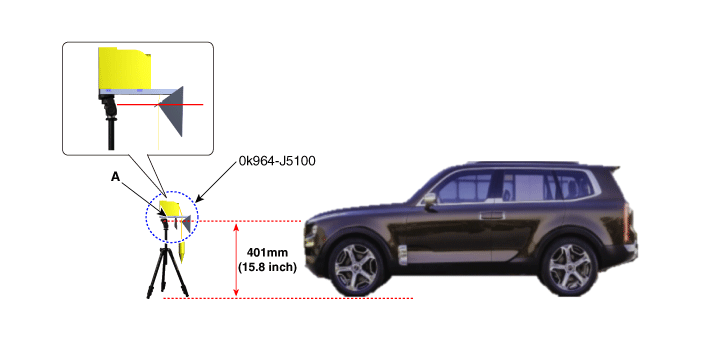
Install the reflector exactly 2.5 m (8.2 ft) from the front of the radar.
The reflector must be installed at the same position (height and angle) as the front radar center. (If the height and angle are different, adjustment cannot be performed correctly.)
Remove objects (metal plates, resin, etc.) that may cause signal interference from the area where front radar alignment is performed.
Be sure to use the special reflector (0K964-J5100).
Make sure the vehicle does not move or vibrate when performing front radar alignment (getting in/out or opening/closing doors).
IG must be ON when performing front radar alignment (engine stopped condition).
Park the vehicle horizontally on level ground.
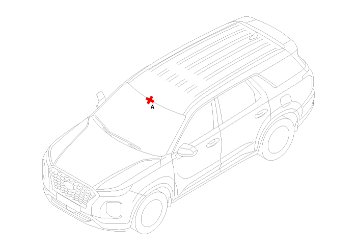
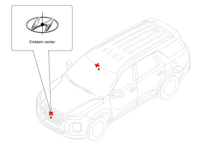
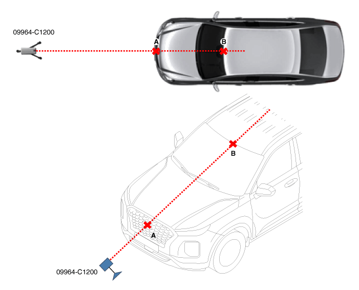
Mark the center point (B) after measuring the distance on the windshield.
Mark the center point of the emblem (A).
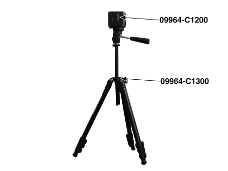
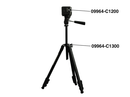
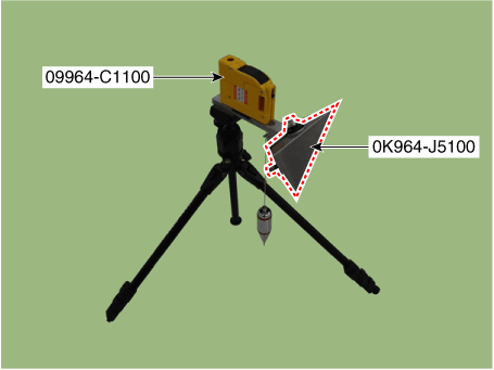
Install the laser (09964-C1200) on the tripod (09964-C1300).
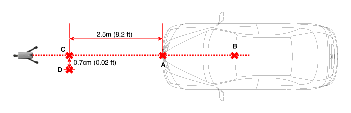
Place the laser (09964-C1200) 2.5 m (8.2 ft) from the front of the vehicle.
Align the vertical laser line with (A) and (B) using the laser (09964-C1200).
Mark (C) 2.5 m (8.2 ft) from (A) in front of the vehicle.
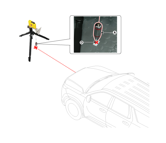
Mark (D) at a point 0.7 cm from (C) in the vertical right direction.
Remove the laser (09964-C1200) from the tripod (09964-C1300).
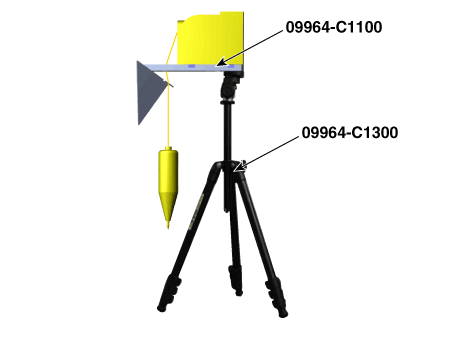
Install the reflector (09964-C1100) on the tripod (09964-C1300).
Install the reflector adapter (0K964-J5100) on the reflector (09964-C1100).
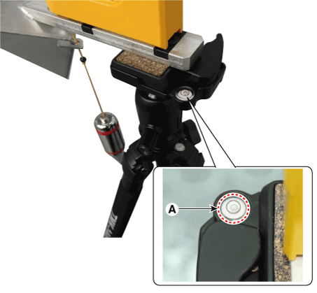
Set the reflector to a horizontal position using the leveler (A) built into the tripod (09964-C1300).
Align the vertical weight (A) of the reflector (09964-C1100) with point (D).
Set the height of the reflector adapter (0K964-J5100) to 401 mm (15.8 in).
Remove the vertical weight from the reflector (09964-C1100).
This may be performed for adjustment if the vertical weight is still remaining.
Visually check the front radar and the front bumper surface again for any objects.
Make sure there is no debris or reflective objects on the radar surface.
Make sure there is no debris or reflective objects on the radiator grille.
Select C1 (stop mode) to check and adjust the front radar alignment angle, following the procedure on the GDS screen.
?
Test yourself
A quick Hyundai Palisade quiz: every answer comes with an explanation and a link to the manual page.