Heating, Ventilation, and Air Conditioning
Dual Automatic Temperature Control (DATC) Unit
In this manual: Heating, Ventilation, and Air Conditioning
9steps
~54min
2/5difficulty
Done 0 of 9
Components and Component Location
Component

Connector Terminal Function
| Connector | PIN No. | Pin Function | Connector | PIN No. | Pin Function |
| A | 1 | Battery | A | 21 | IGN2 |
| 2 | ISG B+ | 22 | IGN1 | ||
| 3 | ILL+ (TAIL) | 23 | Blower Motor (+) | ||
| 4 | REF Sensor Ground (+5 V) | 24 | Photo Sensor (-) _LEFT | ||
| 5 | Mode Control Actuator Feedback | 25 | Photo Sensor (-) _RIGHT | ||
| 6 | Temperature Door Actuator Feedback - Driver | 26 | Incar Sensor (+) | ||
| 7 | Intake Actuator Feedback | 27 | Incar Motor (-) | ||
| 8 | Evaporator Temperature Sensor (+) | 28 | PTC Relay 3 | ||
| 9 | Ambient Temperature Sensor (+) | 29 | PTC Relay 3 | ||
| 10 | Mode Control Actuator (Vent) | 30 | PTC Signal | ||
| 11 | Mode Control Actuator (Defrost) | 31 | Latch Out (-) | ||
| 12 | Temperature Control Actuator (Cool) - Driver | 32 | K-Line | ||
| 13 | Temperature Control Actuator (Warm) - Driver | 33 | P_CAN High | ||
| 14 | Intake Actuator (Fresh Air) | 34 | P_CAN Low | ||
| 15 | Intake Actuator (Recirculation Air) | 35 | MOSFET (Drain L/R) | ||
| 16 | HTD (Rear Defrost) | 36 | MOSFET (Gate) | ||
| 17 | Rear Heater Switch | 37 | ECV + | ||
| 18 | Clean Signal | 38 | ECV - | ||
| 19 | Ionizer Diagnosis | 39 | Sensor Ground | ||
| 20 | ILL - (REO) | 40 | Ground |
| Connector | PIN No. | Pin Function | Connector | PIN No. | Pin Function |
| B | 1 | Temperature Door Actuator Feedback - Passenger | B | 9 | - |
| 2 | Temperature Control Actuator (Cool) - Passenger | 10 | - | ||
| 3 | Temperature Control Actuator (Warm) - Passenger | 11 | - | ||
| 4 | Actuator Feedback Anti-Fog | 12 | Anti-Fog Sensor Temperature Sensor | ||
| 5 | Anti-Fog Actuator (Open) | 13 | Anti-Fog Sensor SCK | ||
| 6 | Anti-Fog Actuator (Close) | 14 | Anti-Fog Sensor Data | ||
| 7 | - | 15 | - | ||
| 8 | Seat PWM Signal - Driver | 16 | Ground |
Repair Procedures
Self-Diagnosis
- Self-Diagnosis Procedure.


- When operating self-diagnosis, the malfunction below (self-diagnosis code) will flash at 0.5 second intervals on the temperature display of the display settings (driver side only), and the other symbols are off.
- Trouble Code Display
- Continuous Operation: DTC.

- Continuous Operation: DTC.

- STEP operation. A. Normal code or one trouble code is the same as continuous operation. B. Trouble code.

- Continuous Operation: DTC.
Display Description of Malfunction Notes 0 Normal 11 Incar Temperature Sensor Open (OPEN, INCAR F/B Voltage ≥ 4.9 V) 12 Incar Temperature Sensor Short (SHORT, INCAR F/B Voltage ≤ 0.1 V) 13 Ambient Temperature Sensor Open (OPEN, AMBIENT F/B Voltage ≥ 4.9 V) 14 Ambient Temperature Sensor Short (SHORT, AMBIENT F/B Voltage ≤ 0.1 V) 17 Evaporator Temperature Sensor Open (OPEN, EVAP F/B Voltage ≥ 4.9 V) 18 Evaporator Temperature Sensor Short (SHORT, EVAP F/B Voltage ≤ 0.1 V) 19 Driver Seat Temperature Control Actuator Open/Short Circuit
(OPEN/SHORT)
SHORT range [TEMP F/B Voltage ≤ 0.1 V]
OPEN range [TEMP F/B Voltage ≥ 4.9 V]20 Driver Seat Temperature Control Actuator Motor Restriction
(Note: if both the target range and the restriction range fall within MAX COOL range [0.1 V < TEMP F/B Voltage ≤ 0.5 V] and MAX WARM range
[4.5 V ≤ TEMP F/B Voltage < 4.9 V], error code 20 is not displayed because
there are no further restrictions. This prevents MAX WARM
and MAX COOL from displaying code 20 due to the allowable tolerance of the actuator
and FATC.)If the actuator cannot reach the required control position within 10 seconds, it is considered restricted. 21 Driver Seat Mode Actuator Feedback Open/Short Circuit
SHORT range [DR MODE F/B Voltage ≤ 0.1 V]
OPEN range [DR MODE F/B Voltage ≥ 4.9 V]22 Driver Seat Mode Actuator Motor Restriction
(Note: if both the target range and the restriction range fall within VENT range [0.1 V < DR MODE F/B Voltage ≤ 0.5 V] and DEF range [4.5 V ≤ DR MODE F/B Voltage < 4.9 V], error code 22 is not displayed because
there are no further restrictions. This prevents VENT and DEF from displaying
code 22 due to the allowable tolerance of the actuator and FATC.)If the actuator cannot reach the required control position within 10 seconds, it is considered restricted. 25 Intake/Recirculation Air Door Actuator Position Sensor Open/Short Circuit
SHORT range [INTAKE F/B Voltage ≤ 0.1 V]
OPEN range [INTAKE F/B Voltage ≥ 4.9 V]26 Intake/Recirculation Air Door Actuator Motor Restriction
(Note: if both the target range and the restriction range fall within FRE range [0.1 V < INTAKE F/B Voltage ≤ 0.5 V] and REC range [4.5 V ≤ INTAKE F/B Voltage < 4.9 V], error code 26 is not displayed because
there are no further restrictions. This prevents FRE and REC from displaying
code 26 due to the allowable tolerance of the actuator and FATC.)32 Passenger Seat Temperature Control Actuator Open/Short Circuit
(OPEN/SHORT)
SHORT range [TEMP F/B Voltage ≤ 0.1 V]
OPEN range [TEMP F/B Voltage ≥ 4.9 V]33 Passenger Seat Temperature Control Actuator Motor Restriction
(Note: if both the target range and the restriction range fall within MAX COOL range [0.1 V < TEMP F/B Voltage ≤ 0.5 V] and MAX WARM range
[4.5 V ≤ TEMP F/B Voltage < 4.9 V], error code 20 is not displayed because
there are no further restrictions. This prevents MAX WARM
and MAX COOL from displaying code 20 due to the allowable tolerance of the actuator
and FATC.)If the actuator cannot reach the required control position within 10 seconds, it is considered restricted. 45 APT CAN signal error 47 RPM CAN Signal Error 48 CAN Vehicle Speed Signal Error 49 Engine coolant temperature CAN signal error - FAIL-SAFE
NO SIGNAL / ITEM Failure Criteria Substitute Value on Failure Notes 1 AMB SENSOR OPEN/SHORT "--" is displayed on the screen. Alternative control until 20 °C 2 INCAR SENSOR OPEN/SHORT Fixed at 25 °C 3 EVA SENSOR OPEN/SHORT Fixed at -2°C 4 TEMPERATURE DOOR POTENTIOMETER OPEN/SHORT If the temperature is set to 22 °C or lower, move to the COOL position and fix it there.
If the temperature is set to 22 °C or higher, move to the WARM position and fix it there.5 MODE DOOR POTENTIOMETER OPEN/SHORT Move to the VENT position and fix it there if VENT mode is on.
Correct the movement of the DEF position if it is not in VENT mode.6 INTAKE DOOR POTENTIOMETER OPEN/SHORT To select FRE, move to the FRE position and fix it there.
For REC, move to the REC position and fix it there.7 VS (Vehicle Speed) FFh or signal not received 1. Take alternative control based on VS_TCU (from TCU2).
2. When both VS and VS_TCU are in FFh state or not received, process vehicle speed as FAIL (alternative control 0 km/h).8 VS_TCU (Vehicle speed calculated by TCU) FFh or signal not received 1. Take alternative control based on VS_TCU (from TCU2).
2. When both VS and VS_TCU are in FFh state or not received, process vehicle speed as FAIL (alternative control 0 km/h).9 N (Engine Speed) No signal received Fixed at 650 rpm 10 F_N_ENG (Engine Speed Signal Error) 01h or no signal received Fixed at 650 rpm 11 TPS (Throttle Position Sensor Signal) FFh or signal not received Fixed at 0% 12 TEMP_ENG (Engine Coolant Temperature) FFh or signal not received Fixed at 90 °C (including calculated torque calculation) 13 R_TqAcnApvC (A/C Compressor Maximum Torque Limit) FFh or signal not received Fixed at 0 N·m 14 R_PAcnC (APT Sensor Output Value) FFh or signal not received Fixed at 0 hPa 15 R_NEngIdlTgC (Engine Idle Target Speed) FFh or signal not received Use the replacement table 16 SUNROOF ON/OFF (C_SunRoofOpenState) No signal received Process the signal to C_SunRoofOpenState=0H (SUNROOF lock). Logic does not operate.)
Replacement
|

|

- Disconnect the negative (-) battery terminal.
- Using a flat-tip screwdriver or a remover, remove the console upper cover (A).

- Press the lock pin and disconnect the various connectors (A).
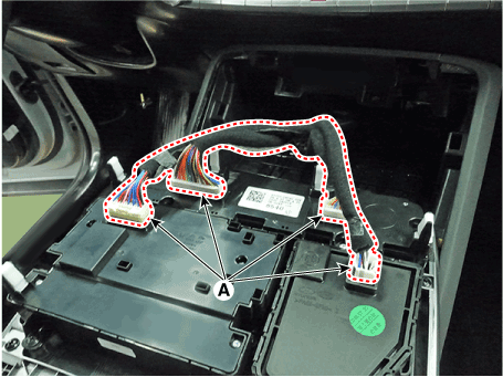
- Loosen the mounting screws and remove the heater and A/C control unit (A).

- To install, reverse the removal procedure.

- Replace any damaged clips (or pin-type retainers).
- Make sure the connector is properly connected.
Test yourself
A quick Hyundai Palisade quiz: every answer comes with an explanation and a link to the manual page.
Was this page helpful?