Turn the ignition OFF and disconnect the negative (-) battery cable.
Turn the steering wheel so that the front wheels are in the straight-ahead position.
Remove the driver airbag module. (Refer to Restraint System - "Driver Airbag Module (DAB) and Clock Spring")
Remove the steering wheel. (Refer to Steering System - "Steering Wheel")
Remove the clock spring. (Refer to Restraint System - "Driver Airbag (DAB) Module and Clock Spring")
Remove the multifunction switch. (Refer to Body Electrical System - "Multifunction Switch")
Remove the steering column lower cover (Refer to Body - "Steering Column Lower Cover").
Remove the emergency pad lower panel. (Refer to Body - "Emergency Pad Lower Panel")
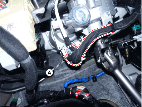
Disconnect the MDPS connector (A).
When connecting the connector, be careful not to bend the pins or allow foreign matter to enter.
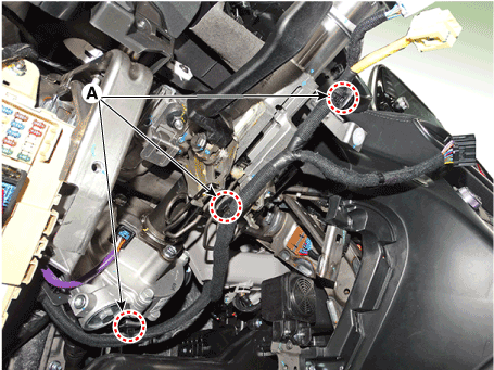
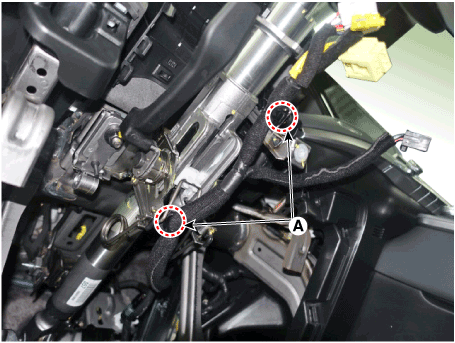
Remove the fixing clip (A), and then disconnect the wiring from the steering column.
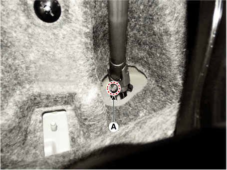
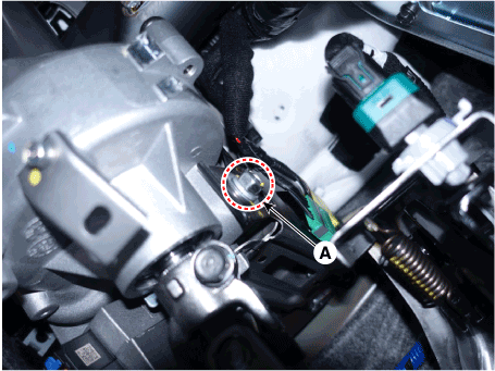
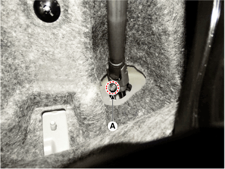
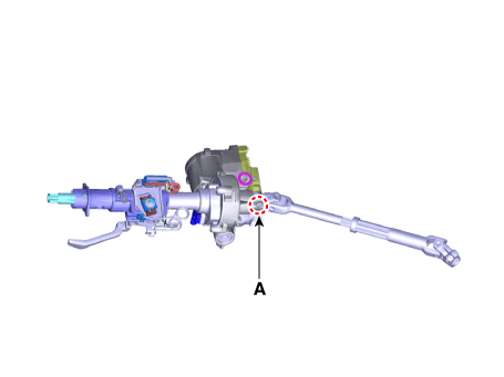
Loosen the bolt (A), then disconnect the universal joint assembly from the steering gear shaft.
Tightening torque: 32.4 - 37 N·m
Do not reuse the bolt.
Lock the steering wheel in the straight-ahead position to prevent damage to the clock spring internal cable.
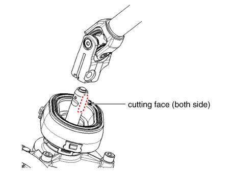
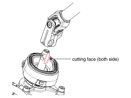
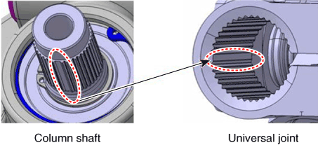
Assemble so that the universal joint hole is fitted to match the cut surface of the pinion shaft.
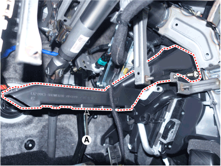
Loosen the mounting screws and remove the air duct [LH] (A).
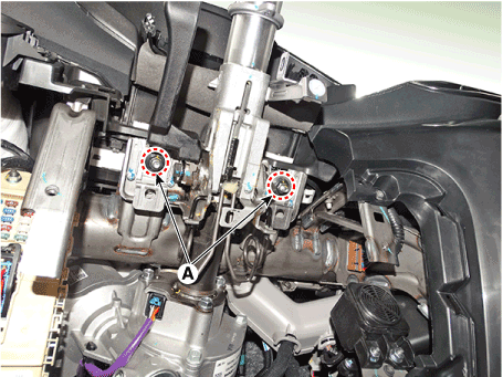
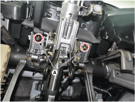
Loosen the mounting nut (A) and bolt (B), and remove the steering column and EPS unit resting on the vehicle floor. Tightening torque (A): 25.0–29 N·m (B): 53.9–59 N·m
Install in the reverse order of removal.
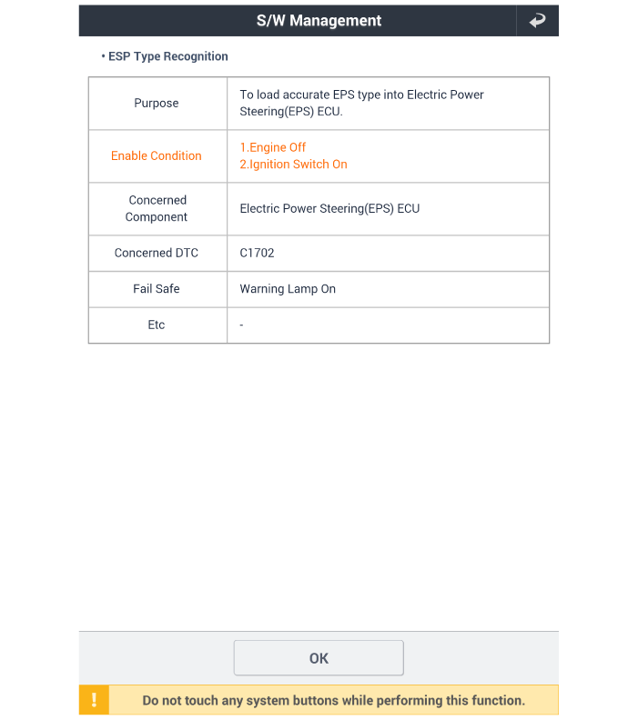
Perform "EPS Type Recognition" using GDS. (Refer to MDPS Motor — "Diagnosis Using GDS")
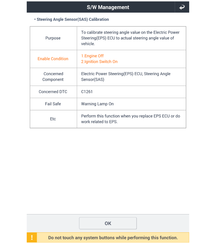
Perform "ASP Calibration" using GDS. (Refer to MDPS Motor — "Diagnosis Using GDS")
Turn the ignition OFF and disconnect the negative (-) battery cable.
Turn the steering wheel so that the front wheels are in the straight-ahead position.
Remove the driver airbag module. (Refer to Restraint System - "Driver Airbag Module (DAB) and Clock Spring")
Remove the steering wheel. (Refer to Steering System - "Steering Wheel")
Remove the clock spring. (Refer to Restraint System - "Driver Airbag (DAB) Module and Clock Spring")
Remove the multifunction switch. (Refer to Body Electrical System - "Multifunction Switch")
Remove the steering column lower cover. (Refer to Body — "Steering Column Lower Cover")
Remove the emergency pad lower panel. (Refer to Body - "Emergency Pad Lower Panel")
Remove the fixing clip (A), and then disconnect the wiring from the steering column.
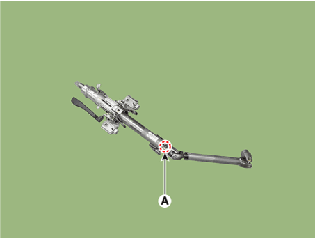
Loosen the bolt (A), then disconnect the universal joint assembly from the steering gear shaft.
Tightening torque: 32.4 - 37 N·m
Do not reuse the bolt.
Lock the steering wheel in the straight-ahead position to prevent damage to the clock spring internal cable.
Assemble so that the universal joint hole is fitted to match the cut surface of the pinion shaft.
Remove the stop lamp switch (Refer to Brake System - "Stop Lamp Switch").
Remove the MDPS unit by loosening the mounting nuts (A) and bolt (B). Tightening torque: (A): 25.0–29 N·m (B): 53.9–59 N·m
Install in the reverse order of removal.
[R-MDPS]
Disassembly
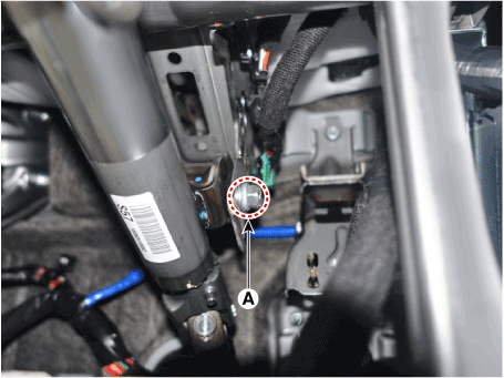
Loosen the bolt (A), then disconnect the universal joint assembly from the steering column assembly.
Tightening Torque: 49.0–59 N·m
[C-MDPS] [R-MDPS]
Do not reuse the universal joint bolt.
Assembly is the reverse of disassembly.
When assembling, align the gear teeth as shown in the illustration below.
Inspection
Inspect the steering column for damage and deformation.
Inspect the steering column for damage and deformation.
Inspect the joint bearing for damage and wear.
Inspect the tilt bracket for damage and cracks.
Check the key lock operation and replace it if necessary.
Diagnosis with GDS
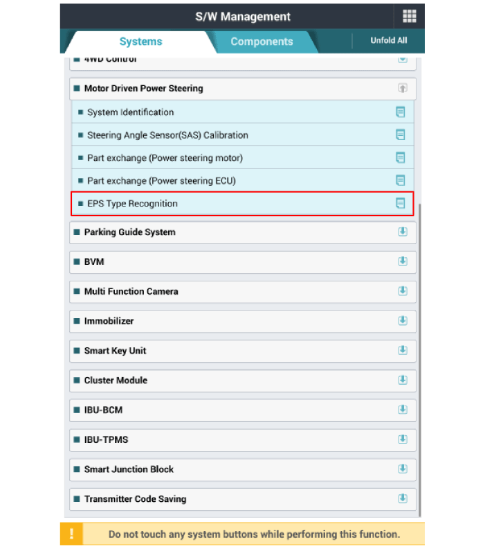
EPS Type Recognition
If EPS type recognition is not performed, a problem will occur with the motor driven power steering performance.
EPS Type Recognition Procedures
Connect the self-diagnosis connector (16-pin) located at the bottom of the driver's side airbag to the self-diagnosis device.
Turn on the scan tool after turning the ignition switch ON.
Turn the steering wheel to the straight-ahead position.
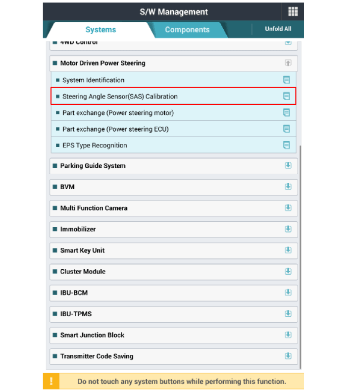
After selecting "Vehicle Model" and "System", select "EPS Type Recognition" on the GDS vehicle selection screen.
Clear the diagnostic trouble code.
Turn the IG switch off and wait at least 20 seconds before starting the engine. Then verify that the MDPS operates correctly. SAS Calibration
The steering angle sensor detects the steering wheel angle and steering angular velocity. The steering wheel angle and steering speed are used to control damping and steering wheel return in addition to providing assist torque.
You can use a scan tool (GDS) to check whether the battery voltage is normal before performing "SAS Calibration".
Make sure no connector is disconnected from the vehicle or the scan tool is disconnected during "SAS Calibration".
After completing "SAS Calibration," turn the IG switch off and wait 10 seconds or more before starting the engine to check operation.
Connect the self-diagnosis connector (16-pin), located in the lower panel on the driver's side, to the diagnostic device.
Turn on the scan tool after turning the ignition switch ON.
Turn the steering wheel to the straight-ahead position.
After selecting "Vehicle Model" and "System," select "SAS Calibration" on the GDS vehicle selection screen.
Clear the diagnostic trouble code.
Turn the IG switch OFF and wait at least 10 seconds before starting the engine. Then check that the MDPS operates correctly.
SAS Calibration Procedures
?
Test yourself
A quick Hyundai Palisade quiz: every answer comes with an explanation and a link to the manual page.