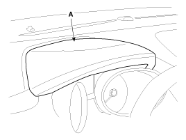
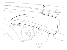
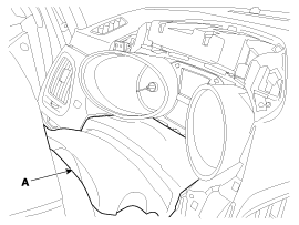
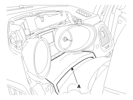
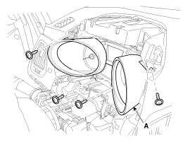
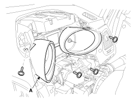
Remove the instrument panel (A) from the housing after loosening the 4 screws. [LH steering wheel][Right-hand drive]
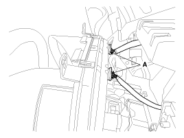
Disconnect the connectors from the instrument cluster front panel (A), then remove the instrument panel.
Installation
Connect the cluster connector.
Install the cluster assembly.
Install the cluster front panel and lower panel.
Inspection
Speedometer
Adjust the tire pressure to the specified level.
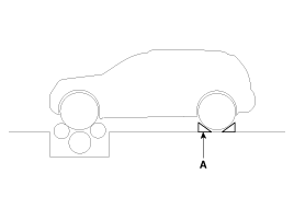
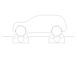
Drive the vehicle onto the speedometer tester. Use wheel chocks (A) as necessary. [2WD] [4WD]
Check that the speedometer reading is within the standard values.
Do not engage the clutch abruptly or increase/decrease speed during the inspection.
Tire wear and excessive or insufficient tire pressure increase the indication error.
[km/h]
Speed (km/h)
20
40
60
80
100
120
Tolerance (km/h)
+4,0 +1,0
+4,0 +1,0
+5,0 +1,5
+6,0 +2,0
+7,0 +2,5
+8,5 +3,5
Speed (km/h)
140
160
180
200
220
-
Tolerance (km/h)
+10,0 +4,5
+11,0 +5,0
+12,0 +6,0
+13,0 +7,0
+14,0 +8,0
-
[mph]
Speed (mph)
10
20
40
60
Tolerance (mph)
+3,0 +1,0
+4,0 +1,0
+5,0 +1,0
+6,0 +2,0
Speed (mph)
80
100
120
140
Tolerance (mph)
+7,0 +3,0
+8,0 +4,0
+9,0 +5,0
+10,0 +6,0
Connect the scan tool to the diagnostic connector or install a tachometer.
With the engine running, compare the tester reading with the tachometer. Replace the tachometer if the tolerance is exceeded.
Reversing the tachometer connections will damage the transistor and diodes inside.
When removing or installing the tachometer, be careful not to drop it or subject it to strong impacts.
Engine Speed (rpm)
Tolerance (rpm)
Max. 8000 rpm
Gasoline
Diesel
1000
±100
±100
2000
±125
±125
3000
±150
±150
4000
±150
±150
5000
±150
±150
6000
±180
±180
7000
±210
-
8000
±240
-
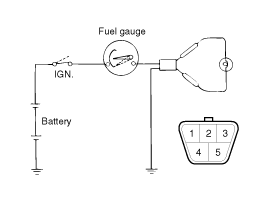
Disconnect the fuel level sender connector from the fuel level sender.
Connect a 12 V, 3.4 W test lamp to terminals 1 and 3 on the harness-side connector.
Turn the ignition ON, then check that the lamp illuminates and the fuel gauge needle is at the maximum mark.
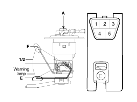
Using an ohmmeter, measure the resistance between terminals 1 and 3 of the sender connector (A) at each float level.
Also check that the resistance changes smoothly when the float moves from "E" to "F".
Position
Liter (x)
Resistance (x)
E
6,5
184 ± 2x
Warning Lamp ON
8,5
170 ± 2x
1/2
28,8
66 ± 2x
F
50
15 ± 2x
If the resistance is out of specification, replace the fuel level sender assembly.
After completing this inspection, wipe the sender dry and reinstall it in the fuel tank.
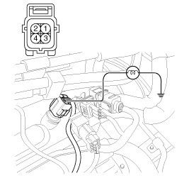
Disconnect the wiring connector (A) from the engine coolant temperature sender in the engine compartment.
Turn the ignition ON. Check that the gauge needle indicates cold. Turn the ignition OFF.
Connect a 12 V, 3.4 W test lamp between terminal No. 2 on the harness-side connector and ground.
Turn the ignition on.
Check that the warning lamp flashes and the needle moves to HOT. If operation does not meet specification, replace the engine coolant temperature gauge. Then recheck the system. Gasoline [G4KD]
Using an ohmmeter, measure the resistance between terminal 2 and ground.
If the resistance value does not match the value in the table, replace the temperature sender.
Temperature [°F(°C)]
131(55)
160(71)
230(110)
257(125)
Calibration Segment
SEG1
SEG3
SEG3
SEG7
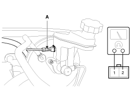
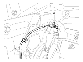
Disconnect the connector (A) from the switch located on the brake fluid reservoir.
Check for continuity between terminals 1 and 2 of the switch while pressing the switch (float) with a rod.
Ignition switch ON.
Release the parking brake.
Disconnect the connector from the brake fluid level warning switch.
Ground the harness-side connector.
Check that the warning lamp illuminates.
Check for continuity between the terminal and the switch body with the switch (A) ON.
Check that there is no continuity between the terminal and the switch body with the switch OFF. If continuity does not meet the specification, replace the switch or check its ground.
Disconnect the connector from the switch.
Check the circuit between the terminals for continuity.
Seat Belt Status
Continuity
Fastened
Non-conductive (xx)
Unfastened
Conductive (x)
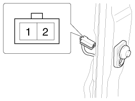
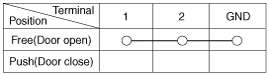
Tachometer Fuel Level Gauge Fuel Level Sender Engine Coolant Temperature Sender Engine Coolant Temperature Sender Brake Fluid Level Warning Switch Brake Fluid Level Warning Lamp Parking Brake Switch Parking Brake Switch, pull type. It is located on the side of the parking brake lever. Door Switch Remove the door switch and check the continuity between the terminals. Seat Belt Switch Seat Belt Warning Lamp With the ignition ON, make sure the lamp illuminates.
Seat Belt Status
Indicator Lamp
Fastened
OFF
Unfastened
ON
?
Test yourself
A quick Hyundai Tucson LM quiz: every answer comes with an explanation and a link to the manual page.