Body Electrical System
Description and Operation
In this manual: Body Electrical System
23steps
~143min
5/5difficulty
1special tools
Done 0 of 23
Description
System Operation: Generally, the Lane Departure Warning is activated at speeds above 70 km/h, but is suppressed when unintentional lane departure occurs and the driver does not operate the turn signal. System Operating Conditions- User Conditions
- When an unintentional lane departure occurs, warnings are generated.
- When the driver activates the turn signal to leave the lane, warnings are not generated.
- Vehicle Condition
- When the vehicle speed exceeds a specified speed, the LDW system is activated.
- When the turn signal is not used, the LDW system is activated.
- Lane Conditions
- If the lane markings are visible and recognizable, the LDWS can operate normally.
- Operation on all roads, including highways, rural roads and urban expressways, at speeds from 70 km/h and with road widths from 2.5 to 5.0 meters.
- Lane material: asphalt roads, concrete roads
- Lane color: white, yellow, blue,
- Temporary lane markings for road repair
- If the lane markings are visible and recognizable, the LDWS can operate normally regardless of season or time of year,
- Operates under partially visible lane markings, such as, and regardless of adverse weather conditions, including rain and wet roads, and time restrictions.
- Operates on a curve with a radius of 250 meters.
- Lane departure warning initial speed: 70 km/h
- Warning initial speed: 70 km/h
- Warning stop speed: 65 km/h
- Warning Method
- Warning Device: Cluster, Buzzer
- Cluster Display Symbols
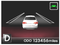
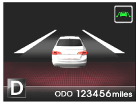
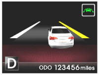
Lane not detected Lane detected and warning system activated. Right-side departure 
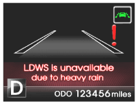
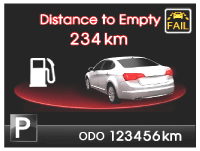
Left-side departure Windshield wiper motor speed above 45 rpm. System Malfunction
※ The displayed symbol and period vary depending on the vehicle LCD and warning signal. (The blinking period can be adjusted.)
- Lane Width (L): If the lane width is 2.5 to 5.0 m (including the North American standard), the departure warning is activated. Also, if the lane width is less than 2.8 m, the departure warning is deactivated.
- Painted Line Width (p): The painted line width is 16 cm (minimum 10 cm, maximum 55 cm). The LDWS can distinguish the left and right lane colors. If technically possible, the LDWS can distinguish lane types such as solid and dotted lines.
- Vehicle Width (W): The vehicle width is determined by the vehicle type.
- Left and Right Standard Lane (Blue, White, Right Yellow) Condition: The standard lane width is 16 cm.
a. 1st Lane Departure Warning: A general lane departure signal, when a vehicle wheel reaches the lane line, is standard equipment. b. Lane Departure Warning Cancellation: When the vehicle leaves the lane toward the opposite lane by more than 40% of the lane width, the warnings are stopped. - Single Line Recognition (Lane): If only one of two lines is recognized, the system provides a lane departure warning using that single line.
- Turn Signal Activated
a. Lane Departure After Turn Signal Activation: If the vehicle leaves the lane after the turn signal is activated, the departure warning in the direction of the turn signal is not activated. The warning signal does not trigger while the turn signal is on. If the turn signal is deactivated during lane departure after being activated, the system may issue a warning after 2 seconds, when it can recognize the lane. If the turn signal is deactivated after lane departure while it was on, the warning signal may be generated after 2 seconds. b. Turn Signal Activated After Lane Departure: The warning is immediately deactivated when the driver activates the turn signal during lane departure. The warning may reactivate 2 seconds after the turn signal is deactivated. - Tracking on a Curve with Radius Less Than 250 m: When the measured curve radius obtained from lane recognition and the yaw rate are less than 250 m, the LDWS does not issue a lane departure warning. The LDWS can recognize road curvature of less than 250 m. (R >= 250 m)
- Lane Unrecognizable
a. During warning, the lane marking becomes unrecognizable. - Lane departure warning, case when one lane becomes unrecognizable: the warning is activated using the previously measured lane width, color and curvature.
- Lane departure warning, when both lanes become unrecognizable: the Lane Departure Warning function stops immediately, and the LDWS signals that the lanes are not recognized to alert the driver to its status.
b. Line Unrecognized. While the vehicle is driving in a lane, if the line is not recognized, the LDWS may issue a lane departure warning using the previous lane width, which is measured from the previous image processing. The LDWS normally relates the color of the lines to the previous recognition result, but if there are any changes in system operation and the ignition is turned on/off, when the system may not determine the lane color, the lane departure warning algorithm assigns the lane color as white. When the system line unrecognized condition persists, the system state changes to the line unrecognized state. b. Both Lanes Not Recognized. The LDWS signals the unrecognized lane status. If there are none of the additional indicators, the system does not indicate the recognition status.
The LDWS may recognize continuous lines as lane markings and has limited lane recognition capability when sharp road curves are encountered. In addition, the system may malfunction in the following cases:
- Lane markings are missing or worn (lane could not be identified).
- Poor visibility due to bad weather conditions.
- Low light or sudden changes in external lighting conditions.
- Sharp road curves (curvature radius less than 250 m).
- Sidewalks and other separating structures along the edge of the lane.
- Dirty windshield (poor camera visibility).
- Necessity. After installation on the vehicle, the LDWS must be calibrated to ensure accurate recognition of road markings. In particular, the system must be calibrated to correct any difference between the ideal road coordinates and the actual road coordinates.
- When replacing the Lane Departure Warning System unit.
- When repairing the roof panel or chassis as a result of a vehicle accident.
- When repairing the LDWS unit mounting bracket.
- The system must be calibrated to correct any vehicle alignment after an accident.
- Schedule: Calibrate after replacing the LDWS and as necessary.
- Condition: After installing the LDWS unit, there must be no error between the ideal road coordinates and the actual road coordinates.
- Purpose: Calibrate the error in the LDWS unit to improve coordinate accuracy.
- Procedure: Perform the calibration procedure using the GDS and the calibration target tool.
- Environment: Place the vehicle on a level surface and align the center of the target to reduce the degree of scattering.
- Calibration Process: Refer to "Calibration Procedures" below.
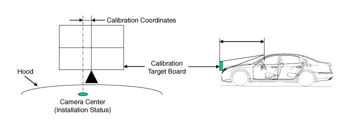
- Install the calibration tool (09890-3N100) on the housing.
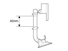
- Install the target on the end of the cap (B) after aligning the center (A) of the target and the emblem.
Tolerance: ± 0.19 in. (± 5 mm)

- Adjust the upper part of the target so that the air bubble (A) is in the center of the circle by bending the target. (For vertical target adjustment)

- Connect the GDS to the vehicle to calibrate the LDWS unit.
- Select the model and the LDWS system.
- Select calibration.
- Perform the calibration automatically.
- Select "LDWS Reference Point Calibration" and perform the calibration procedures.
X-coordinate tolerance ranges: 171 ~ 211, Y: 179 ~ 219


Test yourself
A quick Kia Cadenza VG Owner's Manual quiz: every answer comes with an explanation and a link to the manual page.
Was this page helpful?