Drive Shaft and Axle
Front Propeller Shaft Repair Procedures
In this manual: Drive Shaft and Axle
41steps
~251min
5/5difficulty
1special tools
Done 0 of 41
Replacement
- Loosen the wheel nuts slightly. Raise the vehicle and make sure it is securely supported.
- Remove the front wheel and tire (A) from the front hub.
Tightening torque: 88.2 - 108 N·m
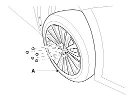
Be careful not to damage the hub bolts when removing the front wheel and tire (A).
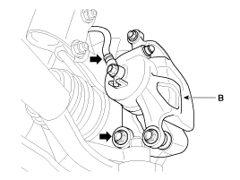
- Remove the brake caliper mounting bolts, then secure the brake caliper assembly (B) with wire.
Tightening torque: 78.4 ~ 98 N·m
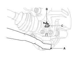
- Disconnect the tie rod end ball joint (A) from the steering knuckle.
- Remove the cotter pin (B).
- Remove the castellated nut (C).
Tightening torque: 34.3 to 44 N·m
- Loosen the mounting bolt and remove the wheel speed sensor (B) from the steering knuckle (A).
Tightening torque: 6.8 - 10.8 N·m

- While applying the brake, remove the drive shaft lock nut (A) from the front hub.
Tightening torque: 274.6 ~ 294 N·m N·m (28.0 ~ 30.0 kgf·m, 202.5 ~ 217.0 ft-lbf)
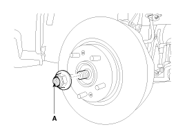
- Always replace the hub lock nut with a new one.
- After installing the lock nut, stake the lock nut using a chisel and hammer, as shown in the illustration below.

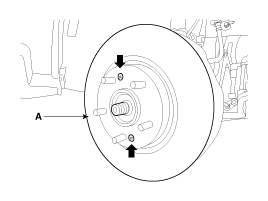
- Loosen the front brake disc set screw and remove the front brake disc (A).
Tightening torque: 4.9 - 5.8 N·m
- Remove the lower arm (A) from the steering knuckle.
Tightening torque: 98.0 ~ 118 N·m
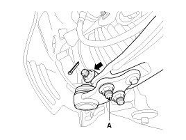
- Remove the front lower arm from the front steering knuckle using SST (0K545-A9100).
- After removing the bolts from the front steering knuckle, install and tighten the body support bolt (A).
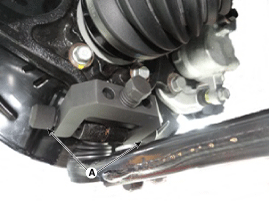
- Insert the auxiliary body (A) between the front steering knuckle and the auxiliary body bolt.
- Tighten the auxiliary body mounting bolt (B) to increase the clearance of the front steering knuckle.

- Install the safety wire (A).

Attach the safety wire to the front strut to prevent the SST from falling and injuring the technician.
- Install the main body between the front strut and the lower arm.

- To prevent the main body from separating, install the locking clamp (A) next to the main body.
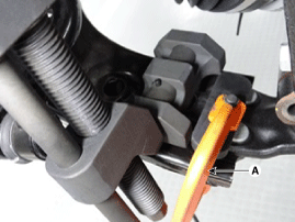
- After installing the locking clamp, turn the handle (B) clockwise until the clamp engages the lower arm.

- Slowly tighten the main body bolt (A) and remove the lower arm from the front steering knuckle.
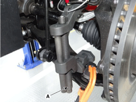
- After removing the bolts from the front steering knuckle, install and tighten the body support bolt (A).
- Disconnect the drive shaft (A) from the front hub assembly.
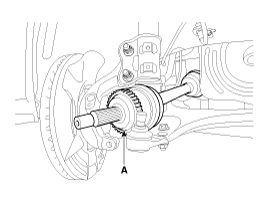
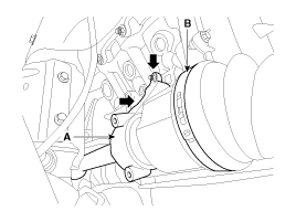
- Remove the drive shaft cover (A).

- Loosen the mounting bolts and remove the inner shaft (A) and the drive shaft assembly (B).
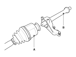
- Disconnect the drive shaft (A) from the inner shaft (B).
- Install in the reverse order of removal.
- Use a pry bar (A), taking care not to damage the transaxle and the joint.
- Do not insert the pry bar (A) too deeply, as this may damage the oil seal.
- Do not pull the propeller shaft with excessive force, as this may cause the components inside the joint assembly to shift, resulting in a torn boot or damaged bearing.
- Plug the transaxle case opening with an oil seal cap to prevent contamination.
- Support the propeller shaft properly.
- Replace the snap ring every time the propeller shaft is removed from the transaxle case.
Inspection
- Inspect the drive shaft boots for damage and wear.
- Inspect the drive shaft splines for wear or damage.
- Make sure there is no water or foreign matter in the joint.
- Inspect the spider assembly for roller rotation, wear, or corrosion.
- Inspect the groove inside the joint case for wear or corrosion.
- Inspect the dynamic damper for damage or cracks.
Disassembly
|
- Remove the snap ring (B) from the spline of the drive shaft (A).

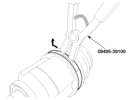
- Remove both boot bands from the transaxle side joint housing (UTJ).

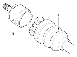
- Pull the boot off the transaxle side joint housing (B).
- While the boot (A) of the transaxle side UTJ is removed, wipe the grease from the UTJ housing (B) and assemble them accordingly.
Make alignment marks on the spider assembly (A), joint case (B), and shaft spline (C) to facilitate reassembly.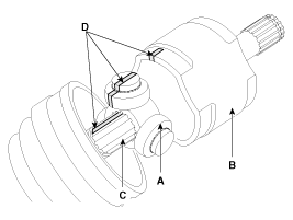
- Remove the snap ring (A) and the spider roller assembly (B) from the shaft.
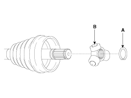
- Clean the spider assembly.
- Remove the transaxle side joint (UTJ) boot (A).
To reuse the boot (A), wrap tape (B) around the drive shaft splines (C) to protect the boot (A).
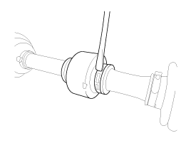
- Using a pry bar or a flat-tip (-) screwdriver, remove both sides of the clip (B) of the dynamic damper (A).
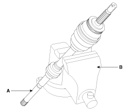
- Secure the drive shaft (A) in a vise (B), as shown in the illustration.
- Apply soap powder to the shaft to prevent damage between the shaft splines and the dynamic damper when the dynamic damper is removed.
- Carefully separate the dynamic damper (A) from the shaft (B).

Installation
- Wrap the drive shaft splines (UTJ) with tape to prevent damage to the boots.
- Apply grease to the wheel side joint boot and install the boot.
- Install the band.
- To install the dynamic damper (A), hold the shaft in a straight line and assemble the dynamic damper using the bands (B).
- Assemble the transaxle side joint boot and bands.
- Using the alignment marks (D) made during removal as a guide, install the spider assembly (A) and snap ring (B) onto the drive shaft splines (C).


- Add the specified grease to the joint boot in the amount that was wiped off during inspection.
- Install both boot bands.
- To control the air in the UTJ boot, maintain the specified distance between the boot bands when they are tightened.
Items Distance (D) mm (in.) Left side Right Side Lambda 3.3 GDI 517,8 (20,39) 531,5 (20,93)

- Using SST (09495-3K000), secure the UTJ bands.

Test yourself
A quick Kia Cadenza VG Owner's Manual quiz: every answer comes with an explanation and a link to the manual page.
Was this page helpful?