Drive the vehicle onto the speedometer tester. Use wheel chocks (A) as necessary.
Check that the speedometer reading is within the standard values.
Do not engage the clutch abruptly or increase/decrease speed during the inspection.
[km/h]
Speed (km/h)
Tolerance (km/h)
Speed (km/h)
Tolerance (km/h)
20
+ 1,30 - 2,70
140
+ 5,51 + 1,51
40
+ 2,00 - 2.00
160
+ 6,21 + 2,21
60
+ 2,70 - 1,30
180
+ 6,91 + 2,91
80
+ 3,40 - 0,60
200
+ 7,61 + 3,61
100
+ 4.11 + 0,11
220
+ 8,32 + 4,32
120
+ 4,81 + 0,81
240
+ 9.02 + 5.02
[MPH]
Speed (mph)
Tolerance (mph)
Speed (mph)
Tolerance (mph)
20
+ 0,81 - 1,67
100
+ 4.07 + 1,59
40
+ 1,63 - 0,85
120
+ 4,89 + 2,41
60
+ 2,45 - 0,04
140
+ 5,71 + 3,23
80
+ 3,26 + 0,78
Connect GDS to the diagnostic connector or install a tachometer.
With the engine running, compare the tester reading with the tachometer. Replace the tachometer if the tolerance is exceeded.
Reversing the tachometer connections will damage the transistor and diodes inside.
When removing or installing the tachometer, be careful not to drop it or subject it to strong impacts.
Engine speed (rpm)
Tolerance (rpm)
Engine speed (rpm)
Tolerance (rpm)
500
± 50
5000
± 100
1.000
± 70
6000
± 100
2000
± 100
7000
± 100
3000
± 100
8000
± 100
4000
± 100
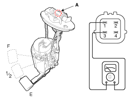
Using an ohmmeter, measure the resistance between terminals 1 and 3 of the sender connector (A) at each float level.
Pin No.
Description
1
Fuel Level Sensor Signal
2
Fuel Pump Motor (+)
3
Fuel Level Sensor Ground
4
Fuel Pump Motor Ground
Also check that the resistance changes smoothly when the float moves from the "E" position to the "F" position. [Standard - Gasoline]
Position
Fuel Level Gauge Needle Angle (Cluster)
Fuel Sender Resistance
E
0 ± 2°
184 Ω
Warning Lamp ON
4 ± 2°
170 Ω
Warning Lamp OFF
15 ± 2°
142 Ω
1/2
60 ± 2°
66 Ω
F
120 ± 2°
15 Ω
[Specification - Gasoline]
Position
Fuel Level Gauge Needle Angle (Cluster)
Fuel Sender Resistance
E
0 ± 2°
184 Ω
Warning Lamp ON
4 ± 2°
170 Ω
Warning Lamp OFF
11,25 ± 2°
142 Ω
1/2
45 ± 2°
66 Ω
F
90 ± 2°
15 Ω
If the resistance is out of specification, replace the fuel level sender assembly.
After completing this inspection, wipe the sender dry and reinstall it in the fuel tank.
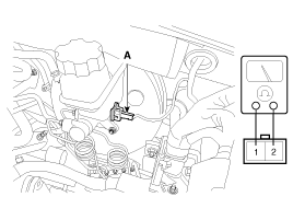
Disconnect the connector (A) from the switch located on the brake fluid reservoir.
Check for continuity between terminals 1 and 2 of the switch while pressing the switch (float) with a rod.
Ignition switch ON
Release the parking brake.
Disconnect the connector from the brake fluid level warning switch.
Ground the harness-side connector.
Check that the warning lamp illuminates.
Check for continuity between the terminal and the switch body with the switch ON (lever pulled up).
Check that there is no continuity between the terminal and the switch body with the switch OFF (lever released). If continuity does not match the specification, replace the switch or check its ground.
Disconnect the connector from the switch.
Check the circuit between the terminals for continuity.
Seat Belt Status
Continuity
Fastened
Non-continuity (∞ Ω)
Unfastened
Continuity (Ω)
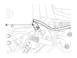
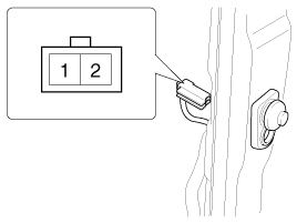
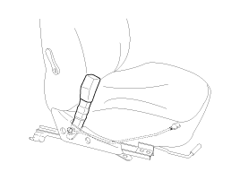
Tachometer Fuel Sender Brake Fluid Level Sensor Brake Fluid Level Warning Lamp Parking Brake Switch Parking Brake Switch (A) is a pull-type switch. It is located under the parking brake lever. To adjust, move the switch bracket up and down with the parking brake lever fully released. Door Switch Remove the door switch and check continuity between the terminals. Seat Belt Switch Seat Belt Warning Lamp With the ignition ON, make sure the lamp illuminates.
Seat Belt Status
Indicator Lamp
Fastened
OFF
Unfastened
ON
Removal
Instrument Cluster
Disconnect the negative (-) battery terminal.
Tilt the steering column down.
Remove the cluster fascia after removing the screws. (Refer to Body - Instrument Panel)
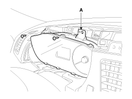
Remove the instrument cluster (A) after loosening the screws.
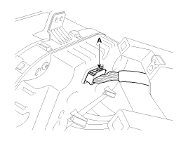
Disconnect the cluster connector (A), then remove the cluster.
Remove the lower driver airbag panel. (Refer to Body - "Driver Airbag Module")
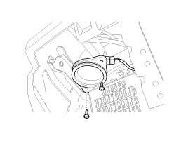
Remove the speaker (A) after removing the screws (2 EA) and the connector.
Speaker
Installation
Instrument Cluster
Install the cluster into the cluster housing.
Install the lower instrument panel cover.
Install the speaker after connecting the connector.
Install the emergency pad lower panel.
Speaker
?
Test yourself
A quick Kia Cadenza VG Owner's Manual quiz: every answer comes with an explanation and a link to the manual page.