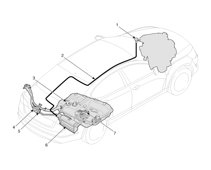
Canister: The canister is filled with activated charcoal and absorbs fuel vapor evaporating in the fuel tank. When the appropriate conditions are met, the ECM/PCM draws the stored fuel vapor from the canister into the intake manifold. Purge Control Solenoid Valve (PCSV): The PCSV is installed in the passage connecting the canister and the intake manifold. It is a duty-type solenoid valve and is controlled by a signal from the ECM/PCM. To draw the absorbed vapor into the intake manifold, the ECM/PCM opens the PCSV; otherwise, the passage remains closed. Fuel Tank Cap: The ratchet tightening device on the threaded fuel tank cap reduces the possibility of incorrect installation and seals the filler neck. When the gasket on the fuel tank cap and the filler neck flange contact each other, the ratchet produces a loud clicking sound, indicating that the cap is properly installed. Fuel Tank Pressure Sensor (FTPS): The FTPS is an integral part of the monitoring system. The FTPS monitors pressure and vacuum level in the fuel tank during PCSV operating cycles, and checks the PCSV and the EVAP system for leaks. Canister Close Valve (CCV): The CCV is located between the canister and the fuel tank air filter. It closes the air inlet to the canister for the EVAP system and prevents fuel vapor from escaping from the canister when the vehicle is not operating. EVAP System Monitoring: The EVAP system monitor consists of a vapor generation stage, an evacuation stage, and a leak check stage. First, the OBD-II system checks whether vapor generation due to fuel temperature is low enough to start monitoring. Then it evacuates the EVAP system through the PCSV with a ramp to maintain a specified vacuum level. The last step is to check that no vacuum is lost due to any leak in the system. Vapor Generation Check: During the stabilization period, the PCSV and CCV are closed. The system pressure is measured as the initial pressure (DP_A). After a specified period (T1), the system pressure (DP_B) is measured again and the difference from the initial pressure is calculated. If this difference (DP_B - DP_A) is greater than the threshold, there is an excessive amount of vapor and the monitor is aborted for the next check. Conversely, if the difference is below another negative threshold, the PCSV is considered faulty, such as stuck open. Evacuation: The PCSV opens with a specified ramp to reach the pressure to a specified level. If the pressure cannot be reduced below the threshold value, the system is judged to have an open fuel tank cap or a large leak. Leak Check: The PCSV closes, and the system waits for some time to obtain stabilized pressure. During the check period (T2), the system measures the start and end pressure in the system (DP_C, DP_D). The diagnostic value is the pressure difference, corrected by the natural vapor generation rate (DP_B - DP_A) from the vapor generation check stage. Component Location
1. Purge Control Solenoid Valve (PCSV) 2. Vapor Line 3. ORVR Valve 4. Fuel Tank Air Filter
5. Canister Close Valve (CCV) 6. Canister 7. Fuel Tank Pressure Sensor (FTPS)
EVAP System MonitoringEvaporative Emission Control System and ORVR System: This system consists of the following items:
Fill Vent Valve
Fuel Cut Valve
Fuel Cut Valve (Roll-Over)
Two-Way Valve (Pressure/Vacuum Relief)
Fuel liquid/vapor separator, installed near the filler neck.
Charcoal canister, installed under the left side member and rear floor protector.
Hoses and Various Connections
When refueling, ambient air is drawn into the filler neck, so that fuel vapor is not released into the air. Fuel vapor in the tank is then forced into the canister through the vent valve. The fuel liquid/vapor separator isolates liquid fuel and passes only clean vapor to the charcoal canister. While the engine is running, the vapor stored in the canister is drawn into the intake manifold and then into the combustion chamber. In this purge process, the charcoal canister is purged and restores its absorption capacity.
1. Fuel Tank Cap 2. Filler Neck 3. Fuel Cut-Off Valve 4. Fuel Tank 5. ORVR Valve 6. 2-Way and Roll-Over Valve 7. Evaporative Hose
8. Evaporative Hose 9. Charcoal Canister 10. Canister Close Valve (CCV) 11. Fuel Feed Line 12. Fuel Tank Pressure Sensor (FTPS) 13. Purge Control Solenoid Valve (PCSV)
?
Test yourself
A quick Kia Cadenza VG Owner's Manual quiz: every answer comes with an explanation and a link to the manual page.