Use fender covers to avoid damaging painted surfaces.
To prevent damage to the cylinder head, wait until the engine coolant temperature drops below normal operating temperature before removing it.
When handling the metal gasket, be careful not to bend the gasket or damage the gasket contact surface.
To avoid damage, carefully disconnect the wiring connectors by holding the connector body.
Turn the crankshaft pulley so that the No. 1 piston is at top dead center.
Label all wires and hoses to avoid incorrect connection.
Remove the engine and transaxle assembly from the vehicle. (Refer to Engine and Transaxle Assembly in this group)
Remove the transaxle assembly. (Refer to Group AT)
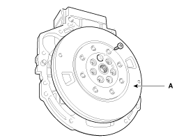
Remove the torsional damper (A).
Install the engine on an engine stand for disassembly.
Remove the intake manifold and exhaust manifold. (Refer to Intake and Exhaust Systems in this group)
Remove the timing chain. (Refer to Timing System in this group)
Remove the cylinder head assembly. (Refer to Cylinder Head in this group)
Remove the balance shaft and oil pump assembly. (Refer to Lubrication System in this group)
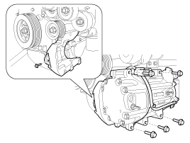
Remove the A/C compressor and bracket assembly. (Refer to Group HA - "Electric A/C Compressor")
Remove the hybrid starter generator (HSG). (Refer to Group HT - "Hybrid Starter Generator")
Remove the water pump assembly. (Refer to Cooling System in this group)
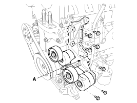
Remove the integrated tensioner assembly bracket (A).
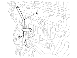
Remove the oil level gauge guide tube (A).
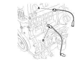
Remove the knock sensor (A) and the oil pressure switch (OPS) (B).
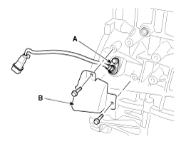
Remove the crankshaft position sensor (CKPS) (A) after removing the cover (B).
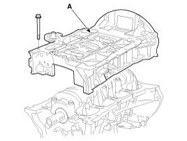
Remove the ladder frame (A).
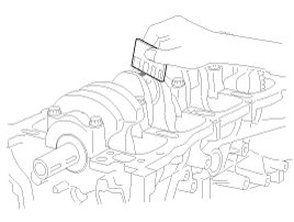
Check the connecting rod side clearance.
Remove the connecting rod caps and inspect the oil clearance.
Remove the piston and connecting rod assembly.
Using a ridge reamer, remove all carbon from the upper part of the cylinder.
Push the piston, connecting rod assembly, and upper bearing out through the top of the cylinder block.
Keep the bearings, connecting rod, and cap together.
Arrange the piston and connecting rod assemblies in the correct order.
Remove the main bearing cap and check the oil clearance.
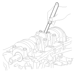
Check the crankshaft end play.
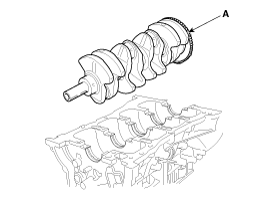
Lift the crankshaft (A) out of the engine, taking care not to damage the journals.
Arrange the main bearings and thrust bearings in the correct order.
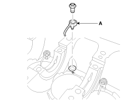
Remove the oil jet (A).
Check the fit between the piston and piston pin. Try moving the piston back and forth on the piston pin. If any movement is felt, replace the piston and pin as a set.
Remove the piston rings.
Using a piston ring expander, remove the 2 compression rings.
Remove the 2 side guides and the spacer by hand.
Arrange the piston rings only in the correct order.
Remove the snap rings, then disconnect the connecting rod from the piston.
Inspection
Connecting Rod
Inspect the connecting rod side clearance. Using a feeler gauge, measure the side clearance while moving the connecting rod back and forth. Side clearance: Standard: 0.10–0.25 mm (0.0039–0.0098 in.) Limit: 0.35 mm (0.0138 in.)
If out of specification, install a new connecting rod.
If still out of specification, replace the crankshaft.
Check the oil clearance of the connecting rod bearing.
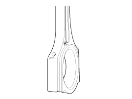
Make sure the alignment marks on the connecting rod and cap are aligned to ensure correct assembly.
Remove the 2 connecting rod cap bolts.
Remove the connecting rod cap and bearing half.
Clean the connecting rod journal and bearing.
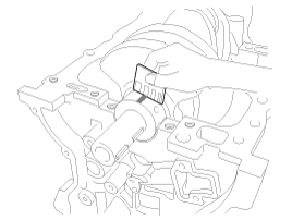
Place a piece of Plastigage across the connecting rod journal.
Install the bearing half and cap in place, then tighten the bolts.
Tightening torque: 17.7 ~ 22 N·m + 88~92°
Always use new connecting rod cap bolts. Connecting rod cap bolts are torque-to-yield bolts designed to stretch permanently beyond the elastic range when tightened. If the bolts are removed and reused, they may break or fail to maintain clamping force.
Do not rotate the crankshaft.
Remove the 2 bolts, the connecting rod cap and the bearing half.
Measure the Plastigage at its widest point.
Standard oil clearance: 0.031 ~ 0.045 mm (0.00122 ~ 0.00177 in.)
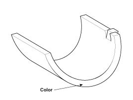
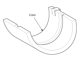
If the Plastigage is too wide or too narrow, remove the upper bearing half, install a new bearing with the same color mark (select the color as shown in the following column), and recheck the clearance.
Do not grind, shim or scrape the bearings or caps to adjust the clearance.
If the Plastigage shows the clearance is still incorrect, try the next larger or smaller bearing (the color above or below the one specified) and recheck the clearance.
If the proper clearance cannot be obtained using bearings of larger or smaller size, replace the crankshaft and start over.
If the markings are illegible due to dirt and dust buildup, do not scrape them off or use a wire brush. Clean them only with solvent or detergent.
Connecting Rod MarkingConnecting Rod Specifications
Grade
Mark
Inner Diameter
a
A
51.000 ~ 51.006 mm (2.00787 ~ 2.00811 in.)
D
B
51.006 ~ 51.012 mm (2.00811 ~ 2.00834 in.)
c
C
51.012 ~ 51.018 mm (2.00834 ~ 2.00858 in.)
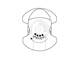
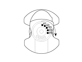
Crankshaft Pin Identification Mark
Stamp in the order shown by the arrow direction from #1.
Crankshaft Specifications
Grade
Mark
Pin Outside Diameter
I
1
47.966 ~ 47.972 mm (1.88842 ~ 1.88866 in.)
II
2
47.960 ~ 47.966 mm (1.88819 ~ 1.88842 in.)
III
3
47.954 ~ 47.960 mm (1.88795 ~ 1.88819 in.)
Connecting Rod Bearing MarkingConnecting Rod Bearing Specifications
Grade
Mark
Bearing Thickness
AA
Blue
1.515 ~ 1.518 mm (0.05965 ~ 0.05976 in.)
A
Black
1.512 ~ 1.515 mm (0.05953 ~ 0.05965 in.)
B
None
1.509 ~ 1.512 mm (0.05941 ~ 0.05953 in.)
C
Green
1.506 ~ 1.509 mm (0.05929 ~ 0.05941 in.)
D
Yellow
1.503 ~ 1.506 mm (0.05917 ~ 0.05929 in.)
Select the connecting rod bearing using the selection table. Connecting Rod Bearing Selection Table
Crankshaft Marking
Connecting Rod Marking
Bearing Classification Assembly
I (1)
A (A)
D (yellow)
B (B)
C (green)
C (C)
B (none)
II (2)
A (A)
C (green)
B (B)
B (none)
C (C)
A (black)
III (3)
A (A)
B (none)
B (B)
A (black)
C (C)
AA (blue)
Inspect the connecting rods.
When reinstalling, make sure the cylinder numbers marked on the connecting rod and cap match those noted during disassembly. When installing a new connecting rod, make sure the bearing locking tabs are on the same side.
Replace the connecting rod if it is damaged on the rod surface at either end. Also, if the steps are worn or the surface is heavily roughened, the small end inside diameter is visible, and the rod must also be replaced.
Using a connecting rod alignment tool, check the connecting rod for bend and twist. If the measured value is close to the repair limit, correct the rod with a press. Any connecting rod that is severely bent or distorted must be replaced. Connecting rod bend limit: 0.05 mm (0.0020 in.) or less per 100 mm (3.94 in.) Connecting rod twist limit: 0.10 mm (0.0039 in.) or less per 100 mm (3.94 in.)
Check the crankshaft bearing oil clearance.
To check the oil clearance between the main bearing and journal, remove the main bearing caps and bearing halves.
Clean each main journal and bearing half with a clean cloth.
Place one strip of Plastigage on each main journal.
Install the bearings and caps in place, then tighten the bolts. Tightening torque 14.7 N·m + 27.5~31 N·m + 120~125°
Always use new crankshaft main bearing cap bolts. Crankshaft main bearing cap bolts are torque-to-yield bolts designed to stretch permanently beyond the elastic range when tightened. If the bolts are removed and reused, they may break or fail to maintain clamping force.
Do not rotate the crankshaft.
Remove the cap and bearing again and measure the widest part of the Plastigage.
Standard oil clearance 0.020 ~ 0,038 mm (0.00079 ~ 0.00150 in.)
If the Plastigage is too wide or too narrow, remove the upper bearing half, install a new bearing with the same color mark (select the color as shown in the following column), and recheck the clearance.
Do not grind, shim or scrape the bearings or caps to adjust the clearance.
If the Plastigage shows the clearance is still incorrect, try the next larger or smaller bearing (the color above or below the one specified) and recheck the clearance.
If the proper clearance cannot be obtained using bearings of larger or smaller size, replace the crankshaft and start over.
If the markings are illegible due to dirt and dust buildup, do not scrape them off or use a wire brush. Clean them only with solvent or detergent.
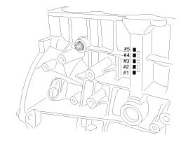
Crankshaft Bore Identification MarkLetters are stamped on the block as size marks for each of the 5 main journal bores. Use them, together with the numbers or bar stamped on the crankshaft (main journal size marks), to select the correct bearings. Cylinder Block Specifications
Class
Mark
Inner Diameter
a
A
56.000 ~ 56.006 mm (2.20472 ~ 2.20496 in.)
D
B
56.006 ~ 56.012 mm (2.20496 ~ 2.20519 in.)
c
C
56.012 ~ 56.018 mm (2.20519 ~ 2.20543 in.)
Crankshaft Journal Identification Mark
Stamp in the order shown by the arrow direction from #1.
Select the crankshaft bearing using the selection table. Crankshaft Bearing Selection Table
Crankshaft Marking
Crankshaft Bore Identification Mark
Bearing Classification Assembly
I (1)
A (A)
D (yellow)
B (B)
C (green)
C (C)
B (none)
II (2)
A (A)
C (green)
B (B)
B (none)
C (C)
A (black)
III (3)
A (A)
B (none)
B (B)
A (black)
C (C)
AA (blue)
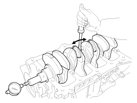
Check the crankshaft thrust clearance. Using a dial indicator, measure the thrust clearance while moving the crankshaft forward and backward with a screwdriver. Standard: 0.07 ~ 0.25 mm (0.0028 ~ 0.0098 in.) Limit: 0.30 mm (0.0118 in.)If the axial play exceeds the maximum, replace the thrust bearings as a set.
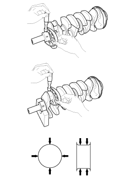
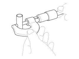
Inspect the main journals and crank pin journals. Using a micrometer, measure the diameter of each main journal and crank pin journal. Main journal diameter: 51.942 ~ 51.960 mm (2.04496 ~ 2.04567 in.) Crank pin journal diameter: 47.954 ~ 47.972 mm (1.88795 ~ 1.88866 in.)
Remove the gasket material. Using a gasket scraper, remove all gasket material from the cylinder block upper surface.
Clean the Cylinder Block. Using a soft brush and solvent, thoroughly clean the cylinder block.
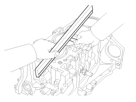
Inspect the top surface of the cylinder block for flatness. Using a precision straightedge and feeler gauge, measure the surface contacting the cylinder head gasket for distortion. Cylinder block gasket surface flatness Standard: Less than 0.05 mm (0.0019 in.) for all. Less than 0.02 mm (0.0007 in.) per 100 mm (3.9370 in.) x 100 mm (3.9370 in.)
Inspect the cylinder bore diameter. Visually check the cylinder for vertical scratches. If deep scratches are found, replace the cylinder block.
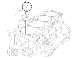
Check the cylinder bore diameter. Using a cylinder gauge, measure the cylinder bore diameter at the positions in both the axial and transverse directions.
Standard diameter 88.00 ~ 88.03 mm (3.4645 ~ 3.4657 in.)
Measuring positions (from the bottom of the cylinder block): 110.7 mm (4.3582 in.) / 160 mm (6.2992 in.) / 210 mm (8.2677 in.)
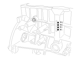
Check the cylinder bore size code on the cylinder block.Cylinder Inner Diameter
Size code
Cylinder Inner Diameter
A
88.00 ~ 88.01 mm (3.4645 ~ 3.4649 in.)
B
88.01 ~ 88.02 mm (3.4649 ~ 3.4653 in.)
C
88.02 ~ 88.03 mm (3.4653 ~ 3.4657 in.)
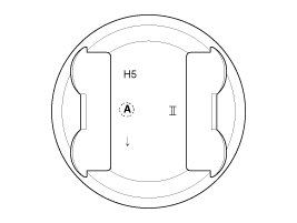
Check the piston size code on the piston top surface.H5: GEM 2.4 L A : Class II : Theta II
Mark the main diameter class with a rubber stamp.
Piston Outer Diameter
Size code
Piston Outer Diameter
A
87.960 ~ 87.970 mm (3.46299 ~ 3.46338 in.)
B
87.970 ~ 87.980 mm (3.46338 ~ 3.46377 in.)
C
87.980 ~ 87.990 mm (3.46377 ~ 3.46417 in.)
Select a piston that matches the cylinder bore size class.
Clearance: 0.030 ~ 0.050 mm (0.00118 ~ 0.00197 in.)
Clean the piston
Using a gasket scraper, remove carbon deposits from the top of the piston.
Using a ring groove cleaner or a broken piston ring, clean the piston ring grooves.
Using solvent and a brush, thoroughly clean the piston.
Do not use a wire brush.
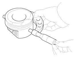
Standard piston outside diameter is measured 17 mm (0.67 in.) from the bottom of the piston.
Standard diameter 87.960 ~ 87.990 mm (3.46299 ~ 3.46417 in.)
Calculate the difference between the cylinder bore diameter and the piston diameter.
Piston-to-cylinder clearance 0.030 ~ 0.050 mm (0.00118 ~ 0.00197 in.)
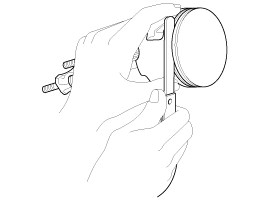
Check the piston ring side clearance. Using a feeler gauge, measure the clearance between a new piston ring and the ring groove wall. Piston ring side clearance Standard No. 1: 0.050 ~ 0.080 mm (0.00197 ~ 0.00315 in.) No. 2: 0.040 ~ 0.080 mm (0.00157 ~ 0.00315 in.) Oil ring: 0.060 ~ 0.125 mm (0.00236 ~ 0.00492 in.) Limit No. 1: 0.100 mm (0.00394 in.) No. 2: 0.100 mm (0.00394 in.) Oil ring: 0.200 mm (0.00787 in.)If the clearance is greater than the maximum, replace the piston.
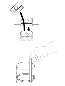
Inspect the piston ring end gap. To measure the piston ring end gap, insert the piston ring into the cylinder bore. Position the ring at a right angle to the cylinder wall, carefully pushing it in with the piston. Measure the gap with a feeler gauge. If the gap exceeds the limit, replace the piston ring. If the gap is too large, recheck the cylinder bore diameter against the wear limits. If the bore exceeds the service limit, the cylinder block must be replaced. Piston ring end gap Standard No. 1: 0.15 ~ 0.30 mm (0.0059 ~ 0.0118 in.) No. 2: 0.37 ~ 0.52 mm (0.0145 ~ 0.0204 in.) Oil ring: 0.20 ~ 0.70 mm (0.0079 ~ 0.0275 in.) Limit No. 1: 0.60 mm (0.0236 in.) No. 2: 0.70 mm (0.0275 in.) Oil ring: 0.80 mm (0.0315 in.)
Measure the clearance between the piston pin and the piston. Piston pin-to-piston clearance 0.003 ~ 0.010 mm (0.00012 ~ 0.00039 in.)
Check the clearance between the piston pin diameter and the connecting rod small end bore. Piston pin-to-connecting rod clearance 0.005 ~ 0.014 mm (0.00020 ~ 0.00055 in.)
Crankshaft, Cylinder Block, Piston and Rings, Piston Pin
Installation
Always use new connecting rod cap bolts. Connecting rod cap bolts are torque-to-yield bolts designed to stretch permanently beyond the elastic range when tightened. If the bolts are removed and reused, they may break or fail to maintain clamping force.
Always use new crankshaft main bearing cap bolts. Crankshaft main bearing cap bolts are torque-to-yield bolts designed to stretch permanently beyond the elastic range when tightened. If the bolts are removed and reused, they may break or fail to maintain clamping force.
Replace all gaskets, O-rings, and oil seals with new parts.
Thoroughly clean all parts to be assembled.
Before installing parts, apply new engine oil to all sliding and rotating surfaces.
Assemble the piston and connecting rod.
Before installing the piston pin, apply a coat of engine oil to the outer surface of the piston pin and the connecting rod.
Be careful not to damage the piston pin during press-fitting.
When replacing the piston pin, check the piston pin outside diameter and the connecting rod small end inside diameter as shown below.
Piston pin outside diameter: 21.997 ~ 22.000 mm (0.86602 ~ 0.86614 in.) Connecting rod small end inside diameter: 22.005 ~ 22.011 mm (0.86634 ~ 0.86657 in.)
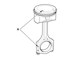
The front mark on the piston and the front mark on the connecting rod (A) must face the engine timing chain side.
Install the piston rings.
Install the oil control ring spacer and 2 side rails by hand.
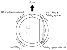
Using a piston ring expander, install the 2 compression rings with the code mark facing up.
Position the piston rings so that the ring end gaps are as shown in the illustration.
Install the connecting rod bearings.
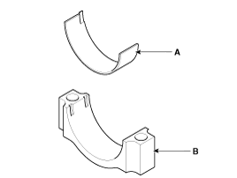
Align the bearing tang with the groove in the connecting rod or connecting rod cap.
Install the bearings (A) into the connecting rod and the connecting rod cap (B).
Be careful not to change the position of the bearing caps.
Install the main bearings.
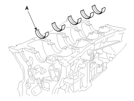
The upper bearings have an oil groove and oil holes; the lower bearings do not.
Align the bearing tang with the tang groove in the cylinder block, then install the 5 upper bearings (A).
Align the bearing tang with the tang groove in the main bearing cap, then install the 5 lower bearings.
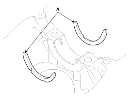
Install the thrust bearings. Install the 2 thrust bearings (A) on both sides of journal No. 3 of the cylinder block so that the oil grooves face outward.
Install the oil jet (A).
Tightening torque: 24.5 - 29 N·m
Install the crankshaft (A) on the cylinder block.
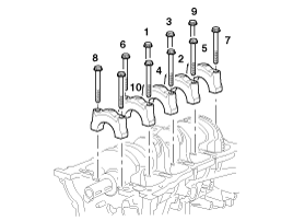
Install the main bearing caps on the cylinder block.
Install the main bearing cap bolts.
Tighten the main bearing cap bolts in 3 steps.
If any bearing cap bolt is broken or deformed, replace it.
Always use new crankshaft main bearing cap bolts. Crankshaft main bearing cap bolts are torque-to-yield bolts designed to stretch permanently beyond the elastic range when tightened. If the bolts are removed and reused, they may break or fail to maintain clamping force.
Apply a thin coat of engine oil to the threads and under the head of the bearing cap bolts.
Using SST (09221-4A000), install and evenly tighten the 10 main bearing cap bolts in several passes in the specified sequence. Tightening torque 14.7 N·m + 27.5~31 N·m + 120~125°
Make sure the crankshaft rotates smoothly.
Check the crankshaft end play.
Install the piston and connecting rod assembly.
Before installing the pistons, apply a coat of engine oil to the ring grooves and cylinder bores.
Remove the connecting rod bearing caps and install short pieces of rubber hose onto the threaded ends of the connecting rod bolts.
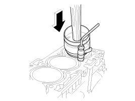
Install the ring compressor, make sure the bearing is securely in place, then place the piston into the cylinder and tap it in using the wooden handle of a hammer.
Stop after the ring compressor is released, and check the connecting rod and journal alignment before inserting the piston into position.
Apply engine oil to the bolt threads. Using SST (09221-4A000), install the connecting rod bearing caps with bearings and tighten the bolts.
Tightening torque: 17.7 ~ 22 N·m + 88~92°
Always use new connecting rod cap bolts. Connecting rod cap bolts are torque-to-yield bolts designed to stretch permanently beyond the elastic range when tightened. If the bolts are removed and reused, they may break or fail to maintain clamping force.
Maintain downward pressure on the ring compressor to prevent the rings from expanding before they enter the cylinder bore.
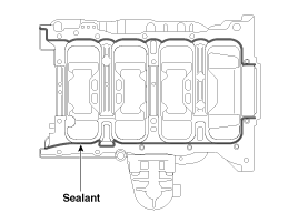
Apply liquid gasket to the mating surfaces of the cylinder block and the ladder frame.
When assembling the ladder frame, apply liquid gasket Loctite 5900H, Threebond 1217H or equivalent.
Assemble the parts within 5 minutes after applying the sealant.
Apply sealant to the internal threads of the bolt holes.
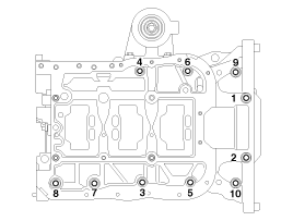
Install the ladder frame (A) with 10 bolts in multiple passes in the sequence shown. Tightening torque: Step 1: 8.8 ~ 9.8 N·m Step 2: 17.7 ~ 21 N·m Step 3: 27.5 ~ 31 N·m
Tighten the bolts in the order shown in 3 steps.
Loosen the bolts in the reverse of the tightening order.
Tighten the bolts in the order shown in 3 steps.
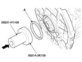
Install the rear oil seal.
Apply engine oil to the lip of the new oil seal.
Using SST (09231-H1100, 09214-3K100) and a hammer, drive in the seal (A) until its surface is flush with the edge of the rear seal retainer.
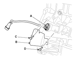
Install the CKPS (Crankshaft Position Sensor) (A) and the sensor cover (B). Tightening torque: CKPS (A): 9.8 ~ 11.8 N·m M6 bolt (C): 9.8 ~ 11.8 N·m M8 bolt (D): 18.6 ~ 24 N·m
Install the OPS (Oil Pressure Switch).
Apply sealant to 2 or 3 threads. Sealant: MS 721-39(B) or equivalent.
Install the oil pressure switch (B).
Tightening torque 7.8 ~ 11.8 N·m
Install the knock sensor (A).
Tightening torque: 18.6 ~ 24 N·m
Install the oil level gauge assembly.
Install a new O-ring onto the oil level gauge.
Apply engine oil to the O-ring.
Install the oil level gauge assembly (A) with the bolt.
Tightening torque 7.8 ~ 11.8 N·m
Install the integrated bracket of the tensioner assembly (A).
Tightening torque: 39.2 ~ 44 N·m
Install the water pump. (Refer to Cooling System in this group)
Install the HSG (Hybrid Starter Generator). (Refer to Group HT - "Hybrid Starter Generator")
Install the air conditioning compressor and bracket assembly. (Refer to Group HA - "Electric Air Conditioning Compressor")
Install the balance shaft and oil pump assembly. (Refer to Lubrication System in this group)
Install the cylinder head assembly. (Refer to Cylinder Head in this group)
Install the timing chain. (Refer to Timing System in this group)
Install the intake manifold and exhaust manifold. (Refer to Intake and Exhaust System in this group)
Remove the engine from the engine stand.
Install the torsional damper (A).
Tightening torque: 117.7 ~ 128 N·m
Always use new bolts.
Apply sealant to the threaded portion (10 mm (0.39 in.) from the end of the bolt) when reusing bolts.
Sealant: Triple Bond 2403, Loctite 200 or 204
Install and evenly tighten the 7 bolts in multiple passes.
Install the transaxle assembly. (Refer to Group AT - "Automatic Transmission")
Install the engine and transaxle assembly to the vehicle. (Refer to Engine and Transaxle Assembly in this group)
Installation is in the reverse order of removal. Add all required fluids and check for leaks. Connect the GDS. Check for DTCs, note them, and clear them. Recheck.
Adjust the shift cable.
Fill the engine with engine oil.
Fill the transmission with fluid.
Fill the radiator and the coolant reservoir with engine coolant.
Fill the inverter radiator and the coolant reservoir with coolant.
Clean the battery terminal posts and cable clamps, then assemble.
Inspect for fuel leaks.
After assembling the fuel line, turn the ignition switch ON (do not operate the starter) so that the fuel pump operates for about two seconds and pressurizes the fuel line.
Repeat this procedure two or three times, then check all fuel line connections for leaks.
Bleed air from the hybrid engine cooling system. (Refer to Group BT - "Engine Coolant")
Bleed air from the engine cooling system.
Start the engine and let it run until warm (until the radiator fan cycles 3 or 4 times).
Turn the engine off. Check the coolant level in the radiator and add coolant if necessary. This allows trapped air to be removed from the cooling system.
Tightly close the radiator cap, then restart the engine and check for leaks.
?
Test yourself
A quick Kia Optima Hybrid Owner's Manual quiz: every answer comes with an explanation and a link to the manual page.