Steering
Steering Column and Shaft Repair Procedures
In this manual: Steering
28steps
~168min
4/5difficulty
Done 0 of 28
Replacement
- Disconnect the negative battery cable from the battery and wait at least 30 seconds.
- Turn the steering wheel so that the front wheels point straight ahead.
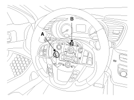
- Press the pin (A) and disconnect the airbag module from the steering wheel.
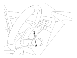
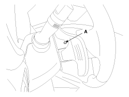
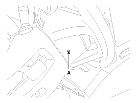
- Disconnect the airbag module connector (A) and horn connector (B), then remove the airbag module from the steering wheel.
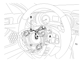
- Disconnect the lock nut (A) and connector (B), then remove the steering wheel from the steering column shaft.
Tightening torque: 39.2 ~ 49 N·m
Do not tap the steering wheel to remove it, as this may damage the steering column.
- Loosen the screw and remove the upper (A) and lower (B) steering column covers.
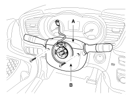
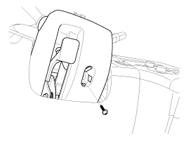
- Disconnect the connector and remove the clock spring (A).
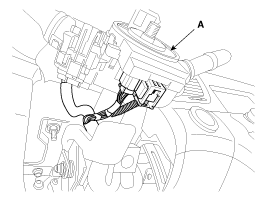
- Disconnect the connector and remove the screw, then remove the multifunction switches (A).
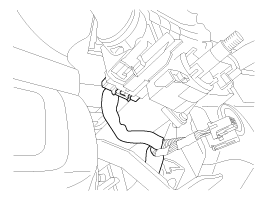
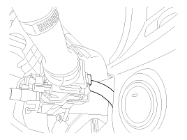
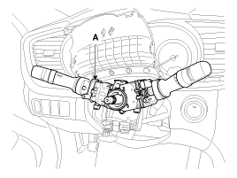
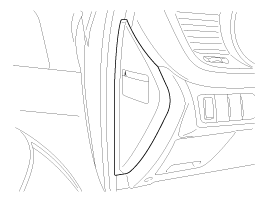
- Remove the lower protector.
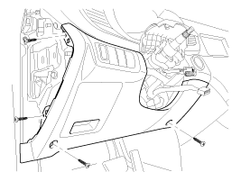
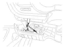
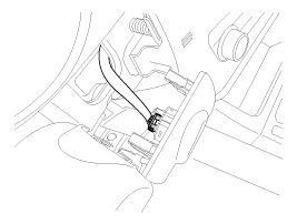
- Loosen the bolt (A) and disconnect the universal joint assembly from the steering gear.
Tightening torque: 29.4 ~ 34 N·m
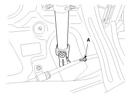
- Do not reuse the bolt.
- Loosen the screw and remove the shower channel (A).
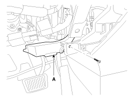
- Disconnect all connectors connected to the steering column.
- Remove the steering column by loosening the mounting bolts and nuts.
Tightening torque: 12.7 - 17.7 N·m
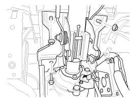
- Installation is the reverse of removal.
- Calibrate the steering angle sensor after replacing the steering column.
Disassembly
Universal Joint Assembly- Loosen the bolt (A) and then disconnect the universal joint assembly from the steering column assembly.
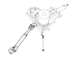
- Assembly is the reverse of disassembly.
- Using a punch, make a groove in the head of the special bolts (A).
- Loosen the special bolt using a screwdriver, then remove the lock assembly from the steering column assembly.
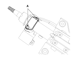
- Assembly is the reverse of disassembly.
Inspection
- Inspect the steering column for damage and deformation.
- Inspect the joint bearing for damage and wear.
- Inspect the tilt bracket for damage and cracks.
- Check the key lock operation and replace it if necessary.
Adjustment
After or before servicing the EPS system, perform the following troubleshooting and inspection procedure. Compare the system condition with the normal condition in the table below. If an abnormal symptom is found, perform the necessary measures and inspection.| Test Conditions | Normal condition: The motor should not provide steering assist. | ||
| Symptom | Possible Cause | Remedy | |
| Ignition OFF | The motor provides steering assist. | ASP is not calibrated. | Perform ASP calibration using the scan tool. |
| IG Power Supply Circuits | Inspect the IG power supply line. | ||
| Test Conditions | Normal condition: The motor should not provide steering assist, and the warning lamp should illuminate. | ||
| Symptom | Possible Cause | Remedy | |
| IG ON / Engine OFF | The motor provides steering assist. | ASP is not calibrated. | Perform ASP calibration using the scan tool. |
| EMS CAN signal not received. | Inspect the CAN line. | ||
| The warning lamp does not illuminate. | Cluster Malfunction | Inspect the cluster and cluster harness. | |
| Test Conditions | Normal condition: The motor provides steering assist, and the warning lamp does not illuminate. | ||
| Symptom | Possible Cause | Remedy | |
| IG ON / Engine ON | The warning lamp illuminates, and the motor does not provide steering assist. | EPS (Battery Power) and IG Power Supply Malfunction | Inspect the connector and harness for EPS (Battery Power) and the IG power supply line. |
| DTC is detected by the system. | Perform a self-diagnosis using a scan tool, and repair or replace as necessary. | ||
| The warning lamp illuminates, and the motor provides steering assist. | ASP is not calibrated. | Perform ASP calibration using the scan tool. | |
| CAN communication error between EPS and cluster. | Inspect the CAN line. | ||
ASP: Absolute Steering Position, CAN: Controller Area Network, EMS: Engine Management System
|
- Before calibrating ASP or recognizing EPS type, check that the battery is fully charged.
- Be careful not to disconnect any cables connected to the vehicle or the scan tool during ASP calibration or EPS type recognition.
- After ASP calibration or EPS type recognition is complete, turn the ignition switch OFF and wait a few seconds, then start the engine to make sure the vehicle operates normally.
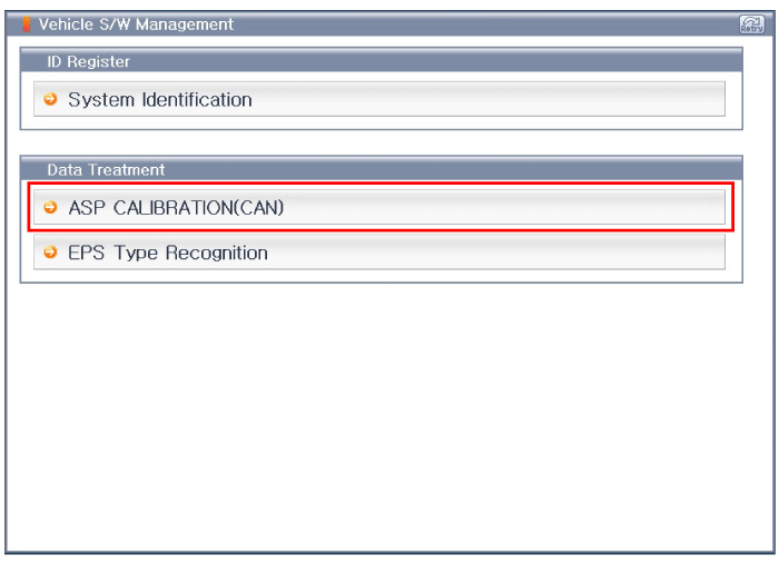
- Select "Steering Wheel Angle Sensor".
- Continue the test in accordance with the instructions on the screen.

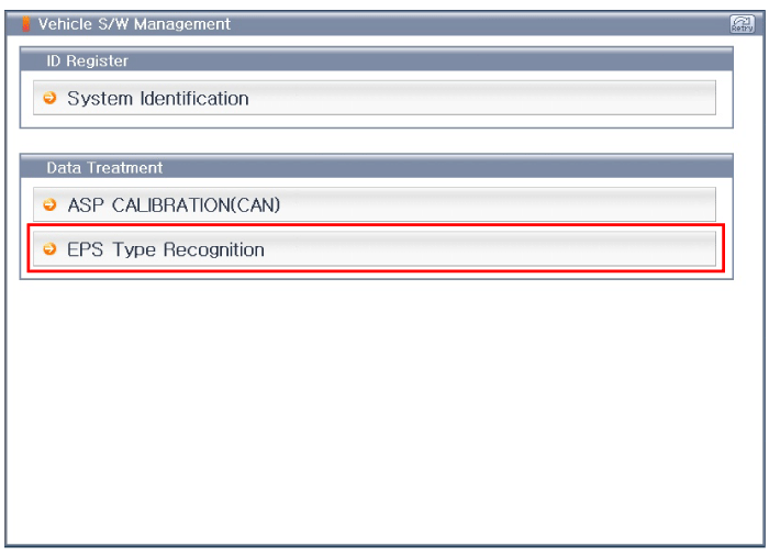
- Select "EPS Variant Coding".
- Continue the test in accordance with the instructions on the screen.

Test yourself
A quick Kia Optima Hybrid Owner's Manual quiz: every answer comes with an explanation and a link to the manual page.
Was this page helpful?