Steering
Steering Gear Repair Procedures
In this manual: Steering
28steps
~168min
4/5difficulty
Done 0 of 28
Replacement
- Remove the front wheel and tire.
Tightening torque: 88.3 ~ 108 N·m
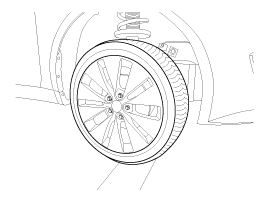
Be careful not to damage the hub bolts when removing the front wheel and tire.
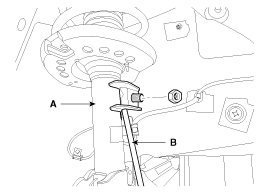
- After loosening the nut, disconnect the stabilizer link (B) from the front strut assembly (A).
Tightening torque: 98.1 ~ 118 N·m
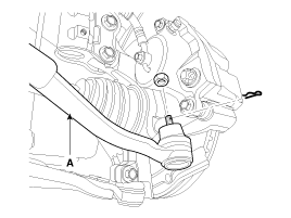
- Remove the cotter pin and castle nut, then disconnect the tie rod end (A) from the front steering knuckle.
Tightening torque: 34.3 ~ 44 N·m
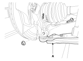
- Loosen the bolt and nut, and remove the lower arm (A).
Tightening torque: 98.1 ~ 118 N·m
- Remove the front lower arm from the front steering knuckle using SST (0K545-A9100).
- After removing the bolts from the front steering knuckle, install and tighten the body support bolt (A).
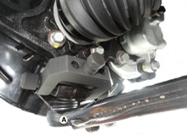
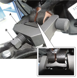
- Insert the auxiliary body (A) between the front steering knuckle and the auxiliary body bolt.
- Tighten the auxiliary body mounting bolt (B) to increase the clearance of the front steering knuckle.
- Install the safety wire (A).
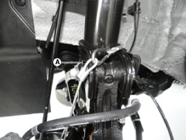
Attach the safety wire to the front strut to prevent the SST from falling and injuring the technician.
- Install the main body between the front strut and the lower arm.
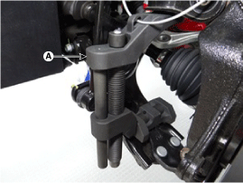
- To prevent the main body from separating, install the locking clamp (A) next to the main body.
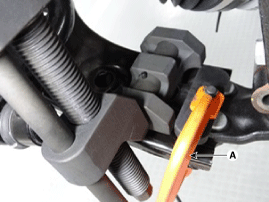
- After installing the locking clamp, turn the handle (B) clockwise until the clamp engages the lower arm.
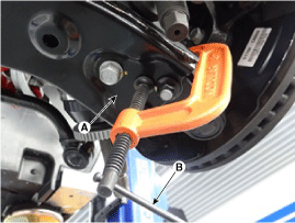
- Slowly tighten the main body bolt (A) and remove the lower arm from the front steering knuckle.
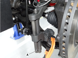
- After removing the bolts from the front steering knuckle, install and tighten the body support bolt (A).
- Loosen the bolt (A) and disconnect the universal joint assembly from the steering gear.
Tightening torque: 29.4 ~ 34 N·m
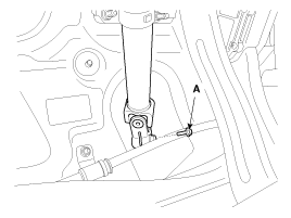
- Hold the steering wheel in the neutral position to prevent damage to the clock spring internal cable when holding the steering wheel.
- Do not reuse the bolt.
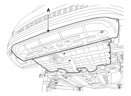
- Remove the lower cover (A).
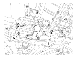
- Loosen the bolt (A) and nut (B), then remove the roller link stopper.
Tightening Torque: 107.9 ~ 128 N·m
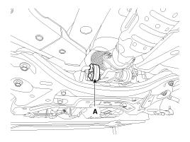
- Disconnect the muffler rubber mount (A).
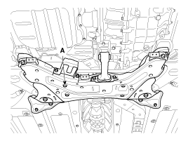
- Loosen the bolts and nuts and remove the subframe (A). Tightening Torque Subframe mounting bolts and nuts: 156.9 ~ 176 N·m (16.0 ~ 18.0 kgf·m, 115.7 ~ 130.2 ft-lbf) Subframe mounting bolts and nuts: 44.1 ~ 59 N·m
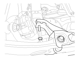
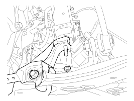
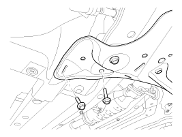
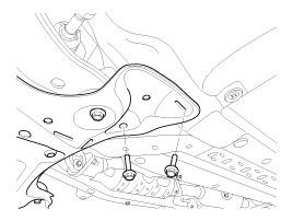
- Remove the stabilizer bar.
- Loosen the bolt and remove the steering gear (A).
Tightening torque: 88.3 ~ 108 N·m
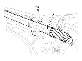
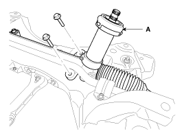
- Installation is the reverse of removal.
Disassembly
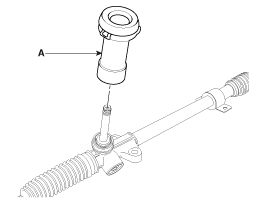
- Remove the dust boot and cover (A) from the gear housing.
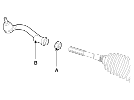
- Loosen the lock nut, then remove the tie rod end (B) and lock nut (A) from the steering cross rod.
- Remove the bellows clamp (A) and band (B), then remove the bellows (C) from the end of the steering cross rod.
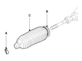
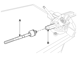
- Remove the tie rod (B) from the rack (A) by unscrewing the inner ball joint of the steering cross rod.
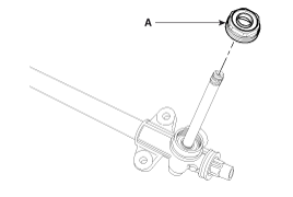
- Remove the plug (A) from the gear housing.
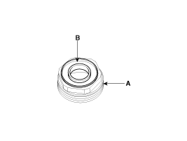
- Remove the oil seal (B) from the plug (A).
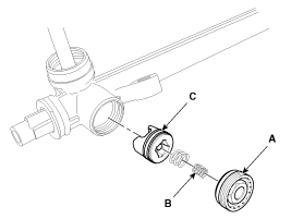
- Remove the clamp plug (A) and spring (B), then pull out the support clamp (C).
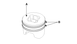
- Remove the O-ring (B) from the yoke plug assembly (A).
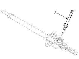
- Pull the pinion assembly (A) out of the gear housing.
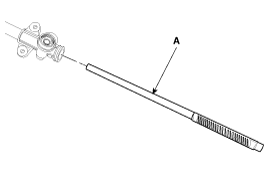
- Pull the rack bar (A) out of the rack housing.
- Assembly is the reverse of disassembly.
Inspection
- Strut bar
- Inspect the rack for damage.
- Inspect the strut bar for bending and deformation.
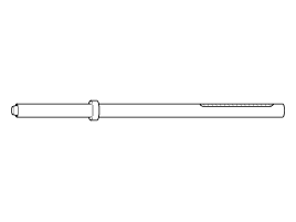
- Gear Assembly
- Inspect the gear for damage.
- Inspect the oil seal for damage.
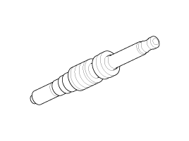
- Inspect the inside of the strut housing for damage.
- Inspect the bellows for tears.
Test yourself
A quick Kia Optima Hybrid Owner's Manual quiz: every answer comes with an explanation and a link to the manual page.
Was this page helpful?