Body Electrical System
Repair Procedures
In this manual: Body Electrical System
26steps
~156min
5/5difficulty
Done 0 of 26
Inspection
Initialization and Diagnostic Sequence Using Diagnostic Equipment. The following is a summary of the A/S procedure using diagnostic equipment. Download Parameter- Select the "AFLS" menu after selecting the vehicle.
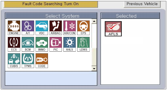
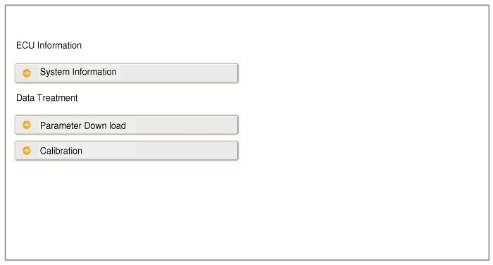
- Select the "Load Parameter" menu to define the vehicle characteristics.
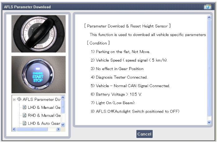
- Select LHD/RHD and MT/AT options according to the vehicle options.
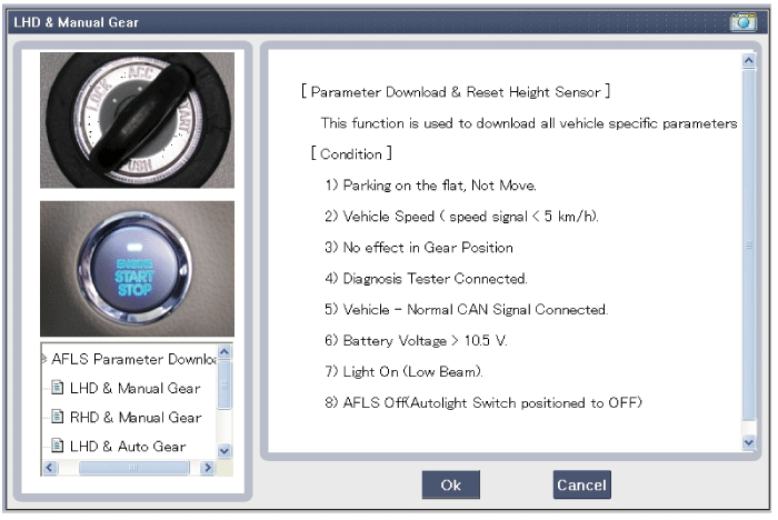
- When "Download Parameter" is completed, the display appears as follows.
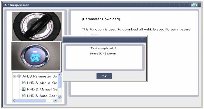
- Select the "AFLS" menu after selecting the vehicle.
- Select "Sensor Initialization - without ECS" if the vehicle has steel suspension.
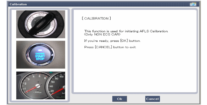
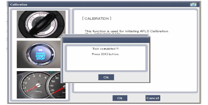
- When "System Calibration" is completed, the display appears as follows.
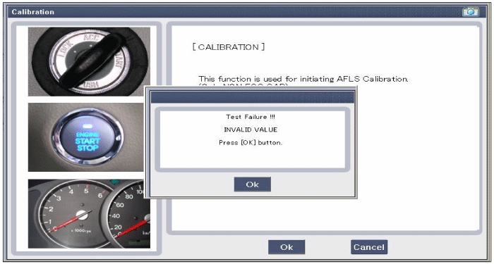
- When "System Calibration" is not completed, the display appears as shown below.
- Select the "AFLS" menu after selecting the vehicle.
- Select "Actuator Test".
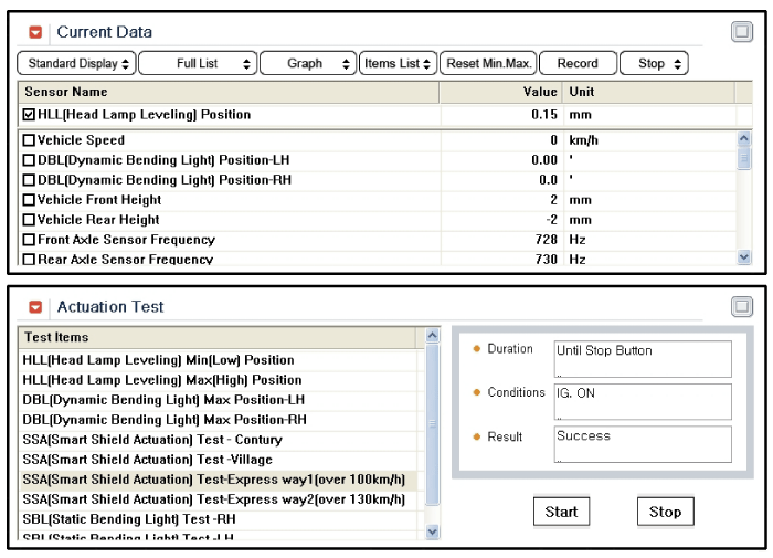
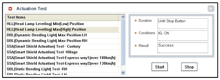
- Select the DBL or HLL test using the "Start" button.
- When DBL or HLL is selected, ACTUATOR DRIVE TO MAX POS (rotary): When the Start button is selected, move to the maximum position in the right direction (15°). When another item is selected: return to the initial position.
| Part | Contents | Fail-safe Response | Symptom Result |
|||
| ECU | ECU Hardware (A/D Converter Failure) |
1) Leveling: Remain at the current POS 2) Swivel: Remain at the current POS |
- | |||
| ECU Software (EEPROM/ROM Failure) |
1) Leveling: Remain at the current POS 2) Swivel: Remain at the current POS |
|||||
| Control Unit Not Initialized Calibration Not Performed |
1) Leveling: Drive to error POS (H-15) 2) Swivel: Drive to error POS (0°) |
|||||
| Leveling Module Failure |
Right | Short Circuit | 1) Right Leveling: Remain at the current POS 2) Left Leveling: Normal operation 3) Swivel: Normal operation |
- | ||
| Over Temperature |
||||||
| LIN Communication Error |
1) Right Leveling: Remain at the current POS (until), move to the error POS 2) Left Leveling: Normal operation 3) Swivel: Normal operation |
|||||
| Left | Short Circuit | 1) Left Leveling: Remain at the current POS 2) Right Leveling: Normal operation 3) Swivel: Normal operation |
- | |||
| Over Temperature |
||||||
| LIN Communication Error |
1) Right Leveling: Normal operation 2) Left Leveling: Remain at the current POS (until), move to the error POS 3) Swivel: Normal operation |
|||||
| Swivel Module Failure |
Right | Short Circuit | 1) Turn right: remain at current POS 2) Turn left: drive to error POS 3) Correct alignment: drive to error POS 4) Left alignment: normal operation |
Sedan | ||
| Overheated | ||||||
| Stall detected | ||||||
| LIN Communication | LIN fault |
Before | 1) Turn: remain at current POS 2) Leveling: drive to error POS |
|||
| After | 1) Turn: drive to error POS 2) Leveling: drive to error POS |
|||||
| Double room supply fault |
Before | 1) Turn: remain at current POS 2) Leveling: drive to error POS |
||||
| After | 1) Turn right: remain at current POS 2) Turn left: drive to error POS 3) Leveling: drive to error POS |
|||||
| Left | Short Circuit | 1) Turn left: remain at current POS 2) Turn right: drive to error POS 3) Left alignment: drive to error POS 4) Correct alignment: normal operation |
Sedan | |||
| Overheated | ||||||
| Stall detected | ||||||
| LIN Communication | LIN fault |
Before | 1) Turn: remain at current POS 2) Leveling: drive to error POS |
|||
| After | 1) Turn: drive to error POS 2) Leveling: drive to error POS |
|||||
| Double room supply fault |
Before | 1) Turn: remain at current POS 2) Leveling: drive to error POS |
||||
| After | 1) Turn left: remain at current POS 2) Turn right: drive to error POS 3) Leveling: drive to error POS |
|||||
| AXLE sensor |
Front & Rear |
External (5V) sensor supply malfunction (short to ground or to battery) |
1) Alignment: drive to error POS 2) Turn: normal operation |
- | ||
| Front | FREQ_LOWER, FREQ_UPPER | 1) Alignment: drive to error POS 2) Turn: normal operation |
||||
| Signal line open circuit | 1) Alignment: drive to error POS 2) Turn: normal operation |
|||||
| Signal line short circuit | ||||||
| Front sensor out of range | ||||||
| Front sensor out of range |
FREQ_LOWER, FREQ_UPPER | 1) Alignment: drive to error POS 2) Turn: normal operation |
||||
| Signal line open circuit | 1) Alignment: drive to error POS 2) Turn: normal operation |
|||||
| Signal line short circuit | ||||||
| Front sensor out of range | ||||||
| Battery | Battery voltage too high | 1) Alignment: remain at current POS (before), move to error POS 2) Turn: remain at current POS (before), drive to error POS |
- | |||
| Battery voltage too low | 1) Alignment: remain at current POS (before), move to error POS 2) Turn: remain at current POS (before), drive to error POS |
|||||
| LIN physical malfunction | Short to battery or GND (physical fault) |
Before | 1) Leveling: Remain at the current POS 2) Swivel: Remain at the current POS |
Sedan | ||
| After | 1) Alignment: drive to error POS 2) Turn: drive to error POS |
|||||
| CAN communication fault |
Speed signal fault |
Vehicle speed signal invalid | 1) Alignment: medium dynamic mode 2) Turn: drive to error POS |
- | ||
| ECU power supply absent on CAN |
||||||
| Steering angle signal fault |
Steering wheel sensor malfunction (invalid signal) |
1) Alignment: normal operation 2) Turn: drive to error POS |
- | |||
| ECU power supply absent on CAN |
||||||
| Transmission signal fault |
Invalid reverse gear signal | 1) Alignment: normal operation 2) Turn: drive to error POS |
- | |||
| ECU power supply absent on CAN |
||||||
| Accelerator pedal signal malfunction | Invalid accelerator pedal signal | 1) Alignment: medium dynamic mode 2) Turn: normal operation |
- | |||
| ECU power supply absent on CAN |
||||||
| Engine status signal fault |
Invalid engine status signal | 1) Alignment: normal operation, no operation (before) 2) Turn: normal operation, no operation (before) |
- | |||
| ECU power supply absent on CAN |
||||||
| Yaw rate signal fault |
Invalid yaw rate signal | 1) Alignment: normal, no operation (before) 2) Turn: reduced performance |
- | |||
| ECU power supply absent on CAN |
||||||
| Brake pedal signal fault |
Brake signal invalid | 1) Alignment: medium dynamic mode 2) Turn: normal operation |
- | |||
| ECU power supply absent on CAN |
||||||
| MAY "Bus off" fault |
ECU isolated from CAN network |
Air suspension | 1) Turn: drive to error POS 2) Alignment: drive to error POS |
- | ||
| Steel suspension |
1) Turn: drive to error POS 2) Alignment: slow dynamic mode |
|||||
| Lamp unit signal error |
ECU power supply not available via CAN | 1) Alignment: normal operation 2) Turn: normal operation |
- | |||
AFLS Setting Procedure: When replacing the AFLS ECU, the H/Lamp Unit or the height sensor, perform the setting procedure using the diagnostic equipment as described below. When performing the AFLS setting procedure, always confirm the suspension type and then load the parameter.
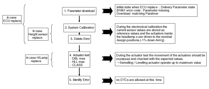
- Vehicle on level surface
- No vehicle movement
- Gear selector in P&N
- Ignition ON and engine speed >500 rpm
- Diagnostic equipment connected
- ALL ECUs on CAN installed and activated
- Battery voltage > 10.5 V (ECU power supply must be ensured)
- Light OFF
- AFLS ON or OFF
- Download delivery parameter
- Check B1661 (parameter missing)
- Ignition OFF.
- Ignition ON and engine speed > 500 rpm
- Download the corresponding parameter
Test yourself
A quick Kia Cee'd quiz: every answer comes with an explanation and a link to the manual page.
Was this page helpful?