Heating, Ventilation, and Air Conditioning
Heater and Air Conditioner Control Assembly (Manual)
In this manual: Heating, Ventilation, and Air Conditioning
5steps
~30min
2/5difficulty
Done 0 of 5
Components and Component Location
Components
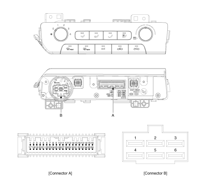
Connector Terminal Function
[Connector A]
| Pin No. | Function | Pin No. | Function |
| 1 | Battery (+) | 21 | IGN2 |
| 2 | ILL+ (TAIL) | 22 | IGN1 |
| 3 | REF Sensor (+5V) | 23 | - |
| 4 | Mode Control Actuator Feedback | 24 | - |
| 5 | Temperature Sensor Feedback | 25 | - |
| 6 | Intake Actuator Feedback | 26 | - |
| 7 | EVAP Sensor (+) | 27 | - |
| 8 | AMB Sensor (+) | 28 | - |
| 9 | - | 29 | CAN High |
| 10 | Maximum Blower Signal | 30 | CAN Low |
| 11 | Blower Signal | 31 | - |
| 12 | Temperature Control Actuator (Warm) | 32 | HTD (Rear Defrost) |
| 13 | Temperature Control Actuator (Cool) | 33 | P_CAN High |
| 14 | Intake Actuator (Recirculation Air) | 34 | P_CAN Low |
| 15 | Intake Actuator (Fresh Air) | 35 | - |
| 16 | Mode Control Actuator (Defrost) | 36 | - |
| 17 | Mode Control Actuator (Vent) | 37 | - |
| 18 | Sensor Ground | 38 | ECV+ |
| 19 | ILL - (REO) | 39 | ECV- (Ground) |
| 20 | Ground | 40 | Ground |
[Connector B]
| Pin No. | Function | Pin No. | Function |
| 1 | Low | 4 | Medium Low |
| 2 | General | 5 | Medium High |
| 3 | Ground | 6 | High |
Repair Procedures
Replacement
Disconnect the negative (-) battery terminal.
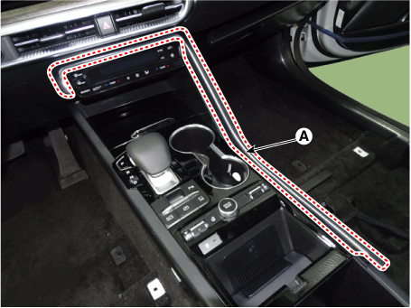
Using a screwdriver or removal tool, remove the upper floor console trim (A).
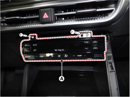
Loosen the mounting screws and remove the heater and air conditioner control assembly (A).
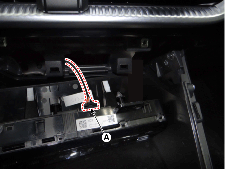
Disconnect the heater and air conditioner control connectors (A).
To install, reverse the removal procedure.
Test yourself
A quick Kia Optima DL3 quiz: every answer comes with an explanation and a link to the manual page.
Was this page helpful?