Heating, Ventilation, and Air Conditioning
Heater Control Unit
In this manual: Heating, Ventilation, and Air Conditioning
6steps
~36min
2/5difficulty
Done 0 of 6
Components and Component Location
Components
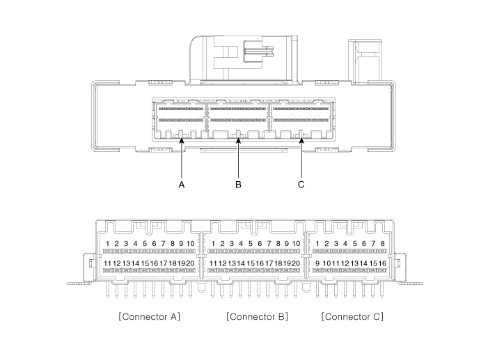
Connector Terminal Function
[Connector A]
| Pin No. | Function | Pin No. | Function |
| 1 | Ground | 11 | Ground |
| 2 | Clean Signal | 12 | - |
| 3 | Humidity | 13 | - |
| 4 | Diagnosis (Ionizer) | 14 | Driver Side Temperature Control Actuator Feedback |
| 5 | Ambient Temperature Sensor (+) | 15 | Passenger Side Temperature Control Actuator Feedback |
| 6 | Evaporator Temperature Sensor (+) | 16 | Intake Actuator Feedback |
| 7 | Right photo sensor (-) | 17 | Mode Control Actuator Feedback |
| 8 | Left photo sensor (-) | 18 | Automatic Anti-Fog Actuator Feedback |
| 9 | CAN Low | 19 | - |
| 10 | CAN High | 20 | - |
[Connector B]
| Pin No. | Function | Pin No. | Function |
| 1 | Passenger Side Temperature Control Actuator (WARM) | 11 | - |
| 2 | Passenger Side Temperature Control Actuator (COOL) | 12 | - |
| 3 | Automatic Anti-Fog Actuator (CLOSED) | 13 | - |
| 4 | Automatic Anti-Fog Actuator (OPEN) | 14 | - |
| 5 | Driver Side Temperature Control Actuator (COOL) | 15 | - |
| 6 | Driver Side Temperature Control Actuator (WARM) | 16 | - |
| 7 | Intake Actuator (REC) | 17 | - |
| 8 | Intake Actuator (FRE) | 18 | Blower Motor (+) |
| 9 | Mode control actuator (DEF) | 19 | FET Drain Feedback |
| 10 | Mode control actuator (VENT) | 20 | PT (GATE) |
[Connector C]
| Pin No. | Function | Pin No. | Function |
| 1 | Battery (+) | 9 | IGN1 |
| 2 | IGN2 | 10 | - |
| 3 | LIN BUS | 11 | - |
| 4 | REF Sensor (+5V) | 12 | - |
| 5 | - | 13 | - |
| 6 | ECV (+) | 14 | - |
| 7 | ECV (-) Ground | 15 | - |
| 8 | Ground | 16 | Sensor Ground |
Repair Procedures
Replacement
Disconnect the negative (-) battery terminal.
Remove the glove box.
(See Body - Glove Box)
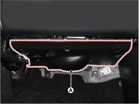
Remove the protective cover under the cover (A).
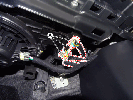
Disconnect the heater control unit connectors (A).
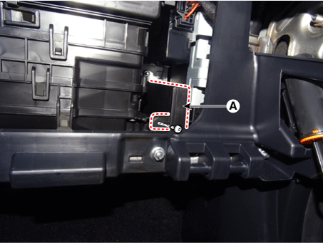
Loosen the mounting screw, then remove the heater control assembly (A).
To install, reverse the removal procedure.
Test yourself
A quick Kia Optima DL3 quiz: every answer comes with an explanation and a link to the manual page.
Was this page helpful?