Front Crossmember Removal/Installation
Performing the following procedures without first removing the ABS wheel-speed sensor may possibly cause an open circuit in the wiring harness if it is pulled by mistake. Before performing the following procedures, disconnect the ABS wheel-speed sensor wiring harness connector (axle side) and fix the wiring harness to an appropriate place where it will not be pulled by mistake while servicing the vehicle.
Secure the steering wheel using tape or a cable to prevent the steering shaft from rotating after disconnecting the steering shaft. If the steering wheel rotates after the steering shaft and the steering gear and linkage are disconnected, the internal parts of the clock spring could be damaged.
1. Remove the joint cover..
2. Disconnect the steering shaft from the steering gear and linkage..
3. Remove in the order indicated in the table.
4. Install in the reverse order of removal.
5. Inspect the wheel alignment and adjust it if necessary..
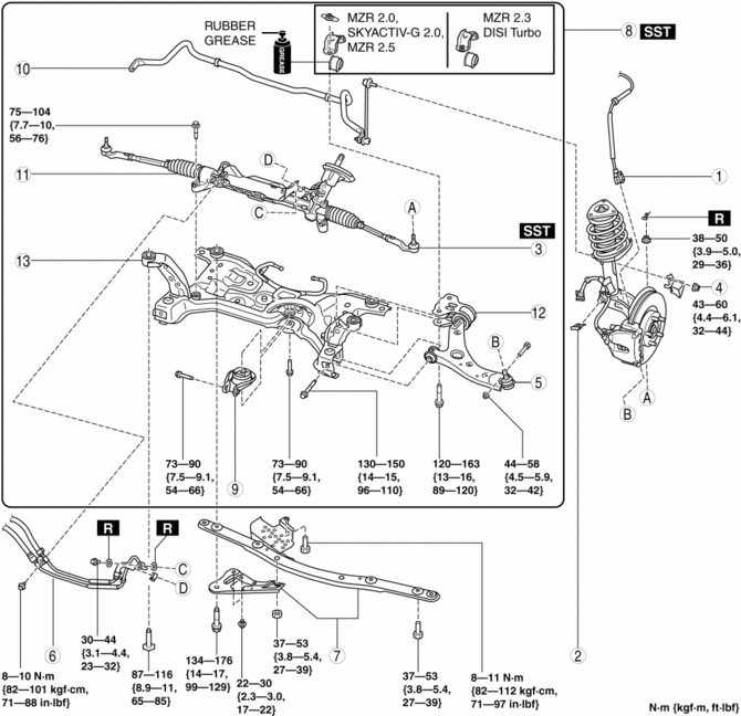
Front ABS wheel-speed sensor wiring harness connector
(See FRONT ABS WHEEL-SPEED SENSOR REMOVAL/INSTALLATION.)
Brake hose clip
Tie-rod end ball joint
(See Tie-rod End Ball Joint Removal Note.)
Front stabilizer control link upper nut
Front lower arm ball joint
(See Front Lower Arm Ball Joint Installation Note.)
Power steering pipe component
Front crossmember bracket
(See Front Crossmember Bracket Removal Note (SKYACTIV-G 2.0).)
Front crossmember component
(See Front Crossmember Component Removal Note.)
(See No. 1 Engine Mount Rubber and Front Crossmember Component Installation Note.)
No.1 engine mount rubber
(See No. 1 Engine Mount Rubber and Front Crossmember Component Installation Note.)
Front stabilizer
(See FRONT STABILIZER REMOVAL/INSTALLATION [MZR 2.0, SKYACTIV-G 2.0, MZR 2.5].)
(See FRONT STABILIZER REMOVAL/INSTALLATION [MZR 2.3 DISI Turbo].)
Steering gear and linkage
(See STEERING GEAR AND LINKAGE REMOVAL/INSTALLATION.)
Front lower arm
(See FRONT LOWER ARM REMOVAL/INSTALLATION.)
Front crossmember
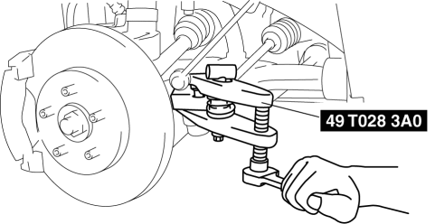
Tie-rod End Ball Joint Removal Note 1. Detach the tie-rod end from the steering knuckle using the SST
.
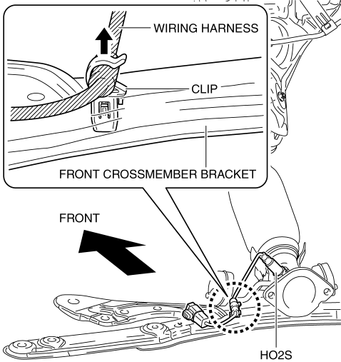
Front Crossmember Bracket Removal Note (SKYACTIV-G 2.0)
1. Disconnect the wiring harness connecting to the front crossmember bracket.
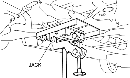
Front Crossmember Component Removal Note WARNING:
Removing the crossmember is dangerous. The crossmember component could fall and cause serious injury or death. Verify that the jack securely supports the crossmember component.
1. Support the front crossmember component using a jack.
2. Detach the rubber hangers from the front crossmember.
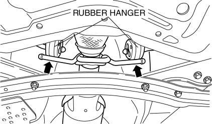
3. Remove the front crossmember, front stabilizer, front lower arm, and steering gear and linkage as a single unit.
No. 1 Engine Mount Rubber and Front Crossmember Component Installation Note 1. Verify the left and right identification marks and install the positioning SSTsto the front crossmember.
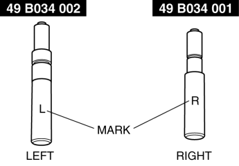
NOTE:
- Verify the identification marks before installation because the left and right parts of the SSTs
have different shapes.
2. Temporarily tighten the No.1 engine mount rubber to the front crossmember.
3. Raise the transmission jack gradually and install the front crossmember to the vehicle. At this point verify that the SSTsis securely inserted in the positioning holes on the body.
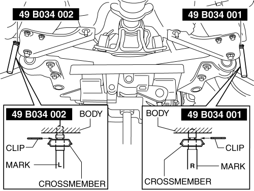
WARNING:
The front crossmember component could fall and cause serious injury or death. Verify that the jack securely supports the front crossmember component.
4. Tighten the front crossmember installation bolts and nuts.
5. Tighten the bolts in the order shown in the figure.
MZR 2.0, MZR 2.3 DISI Turbo, MZR 2.5
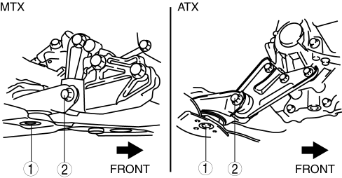
SKYACTIV-G 2.0
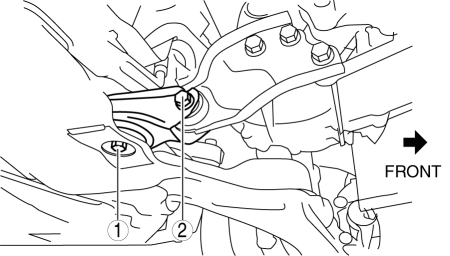
CAUTION:
Tighten the bolts in the order shown in the figure to prevent abnormal noise and vibration after assembly.
Tighten the bolts while being careful of their length to prevent interference between the steering gear housing and bolt.
- Tightening torque
73—90 N·m {7.5—9.1 kgf·m, 54—66 ft·lbf}
- Bolt stem length
Front crossmember side: 62 mm {2.4 in}
No.1 engine mount bracket side: 65 mm {2.6 in}
The bolt insertion direction can be either front or rear of the vehicle, however, keep the insertion direction the same on both the left and right sides of the vehicle.
Test yourself
A quick Mazda 3 quiz: every answer comes with an explanation and a link to the manual page.