Braking system
Dsc hu/cm inspection
In this manual: Braking system
~2min read
1. Remove the battery and battery bracket.
2. Disconnect the DSC HU/CM connector.
3. Connect the SST(49 G066 004) to the DSC HU/CM connector and harness side connector.
4. Inspect voltage referring the table below.
Terminal Voltage Table (reference value)(Ignition switch is at ON, and connector is connected unless indicated otherwise.)
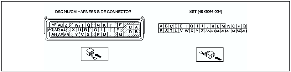
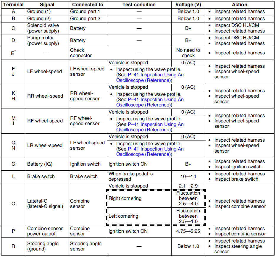
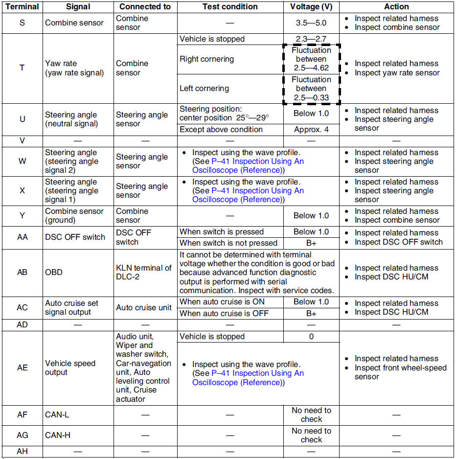
* : Used for vehicle manufacturing, not used for DSC.
Inspection Using An Oscilloscope (Reference) Steering angle (steering angle signal 1 and 2)- DSC HU/CM terminal:
Steering angle signal 2 : W ( + ) - R ( - )
Steering angle signal 1 : X ( + ) - R ( - )
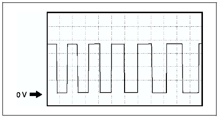
- Oscilloscope setting:
1 V/DIV (Y), 25 ms/DIV (X), DC range
- Vehicle condition: Rotating steering wheel at one revolution per second
- As steering wheel rotation speed increases, period of wave shortens.
- As for shape of steering angle signals 1 and 2, the phase is different.
- DSC HU/CM terminal:
RF : M ( + ) - I ( - )
RR : K ( + ) - H ( - )
LF : F ( + ) - J ( - )
LR : Q ( + ) - N ( - )
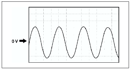
- Oscilloscope setting:
1 V/DIV (Y), 2 ms/DIV (X), AC range
- Vehicle condition: Driving 30 km/h
- As vehicle speed increases, period of wave shortens.
- If there is malfunctioning in the sensor rotor, wave profile warps.
- DSC HU/CM terminal: AE ( + ) - A( - )
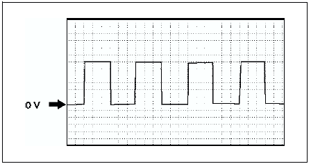
- Oscilloscope setting:
1 V/DIV (Y), 5 ms/DIV (X), DC range
- Vehicle condition: Driving 30 km/h
- As vehicle speed increases, period of wave shortens.
Test yourself
A quick Mazda 6 quiz: every answer comes with an explanation and a link to the manual page.
Was this page helpful?