Suspension Arm
Exploded View
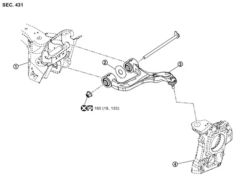
 |
Frame |  |
Stopper rubber |  |
Suspension arm |
 |
Axle housing | ||||
 |
: Always replace after every disassembly. | ||||
 |
: N·m (kg-m, ft-lb) | ||||
Removal and Installation
REMOVAL
Without Dynamic Digital Suspension and Electronic Air Suspension
Remove tires. Refer to ROAD WHEEL TIRE : Removal & Installation.
Loosen rear lower link mounting nuts (frame side).
Set suitable jack under axle housing.
Remove shock absorber mounting bolts from front lower link. Refer to Removal and Installation.
Remove stabilizer clamp mounting bolts. Refer to Removal and Installation.
Remove shock absorber. Refer to Removal and Installation.
Separate suspension arm from axle housing. Refer to Removal and Installation.
Remove suspension arm mounting bolt, nut, and stopper rubber from frame, and remove suspension arm.
Perform inspection after removal. Refer to Inspection.
With Dynamic Digital Suspension and Electronic Air Suspension
Start engine.
Turn auto height mode control switch to ON, shift the shift position to N and set to normal height.
Turn OFF the electronic air suspension function. Refer to Operation.
Stop engine.
Lift up the vehicle.
Remove rear tire. Refer to ROAD WHEEL TIRE : Removal & Installation.
Remove wheel sensor and harness connector. Move wheel sensor in a place where it will not interfere with work. Refer to Removal and Installation.
Disconnect shock absorber harness connector.
Support the rear lower link with suitable jack (A) until most horizontal angle with vehicle on the ground.
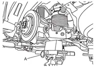
Loosen the air connector and perform air bleeding.
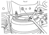
Remove air tube together with air connector from air spring .
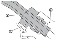
Remove cylinder body. Hang cylinder body in a place where it will not interfere with work. Refer to Removal and Installation.
Loosen rear lower link mounting nuts (frame side).
Separate rear lower link from axle housing. Refer to Removal and Installation.
Set suitable jack under axle housing.
Remove shock absorber mounting bolts from front lower link. Refer to Removal and Installation.
Remove stabilizer clamp mounting bolts. Refer to Removal and Installation.
Remove shock absorber. Refer to Removal and Installation.
Separate suspension arm from axle housing. Refer to Removal and Installation.
Remove suspension arm mounting bolt, nut, and stopper rubber from frame, and remove suspension arm.
Perform inspection after removal. Refer to Inspection.
INSTALLATION
Without Dynamic Digital Suspension and Electronic Air Suspension
Note the following, and install in the reverse order of removal.
Perform final tighting of suspension arm (frame side) by the following procedures.
Measure between wheel center and fender arch (A).
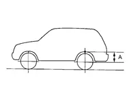
Set the wheel chocks on the front tires.
Jack up the rear of the vehicle and set the rigid rack.
Remove the rear tires.
Set suitable jacks (A) on the left and right axle housings
. (axle housing ball joint fastening part).
Jack up the left and right axle housings until the vehicle no longer floats off the rigid rack (A).
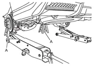
Measure between wheel center and fender arch (A).
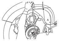
Tight the mounting nuts of suspension arm (frame side) to the specified torque. Refer to Exploded View.
Perform inspection after installation. Refer to Inspection.
With Dynamic Digital Suspension and Electronic Air Suspension
Install suspension arm mounting bolt, nut, and stopper rubber to frame, and install suspension arm.
Install suspension arm to axle housing. Refer to Removal and Installation.
Install shock absorber to front lower link. Refer to Removal and Installation.
Install stabilizer clamp mounting bolts. Refer to Removal and Installation.
Install rear lower link to axle housing. Refer to Removal and Installation.
Tighten rear lower link mounting nuts (frame side). Refer to Removal and Installation.
Install cylinder body. Refer to Removal and Installation.
Install air tube and air connector together to air spring .
Start engine.
Use CONSULT and fill the inner pressure of air spring to 3.3 bar. Refer to Work Support.
Remove suitable jack from rear lower link.
Use CONSULT and fill the inner pressure of air spring to 3.3 bar. Refer to Work Support.
Install shock absorber harness connector.
Stop engine.
Install rear tire. Refer to ROAD WHEEL TIRE : Removal & Installation.
Lift down the vehicle.
Start engine.
Perform pressure measurements using CONSULT. Refer to Work Support.
Perform the height sensor calibration using CONSULT. Refer to Work Support.
Use CONSULT and vehicle to the normal height. Refer to Work Support.
Turn ON the electronic air suspension function. Refer to Operation.
Stop engine.
Perform final tighting of suspension arm (frame side) by the following procedures.Measure between wheel center and fender arch (A).
. (axle housing ball joint fastening part).
Perform inspection after installation. Refer to Inspection.
Inspection
INSPECTION AFTER REMOVAL
Appearance
Check the following items, and replace the part if necessary.
Suspension arm and bushing for deformation, cracks or damage.
Boot of ball joint for cracks or damage, and also for grease leakage.
Ball Joint Inspection
Manually move ball stud to confirm it moves smoothly with no binding.
Swing Torque Inspection
Move the ball joint at least ten times by hand to check for smooth movement.
Hook spring balance (A) at groove. Confirm spring balance measurement value is within specifications when ball stud begins moving.

| Swing torque | : Refer to Ball Joint. |
If swing torque exceeds the standard range, replace suspension arm assembly.
Rotating Torque Inspection
Move the ball joint at least ten times by hand to check for smooth movement.
Attach mounting nut to ball stud. Check that rotating torque is within specifications with a preload gauge [SST: ST3127S000 (NI-25765-A)] (A).
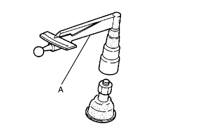
| Rotating torque | : Refer to Ball Joint. |
If rotating torque exceeds the standard range, replace suspension arm assembly.
Axial End Play Inspection
Move the ball joint at least ten times by hand to check for smooth movement.
Move tip of ball stud in axial direction to check for looseness.
| Axial end play | : Refer to Ball Joint. |
If axial end play exceeds the standard range, replace suspension arm assembly.
INSPECTION AFTER INSTALLATION
Without Dynamic Digital Suspension and Electronic Air Suspension
Check wheel alignment. Refer to Inspection.
With Dynamic Digital Suspension and Electronic Air Suspension
Make sure the electronic air suspension function is turn ON. Refer to Operation.
Confirm that no warning message is displayed on the information display. Refer to Air suspension warning.
Perform the self-diagnosis with CONSULT. Check if any DTC is detected. Refer to CONSULT Function.
Confirm to close the hood.
Always check for the air leakage with soapy water.
Check wheel alignment. Refer to Inspection.