Transaxle & transmission CVT: RE0F10B

Diagnosis and repair workflow

In this manual: Transaxle & transmission CVT: RE0F10B
Foreword — 1General information — 45Engine Mechanical MR16DDT — 61Engine Mechanical HR16DE — 52Engine Mechanical K9K — 46Engine Lubrication System MR16DDT — 18Engine Lubrication System HR16DE — 14Engine Lubrication System K9K — 11Engine Cooling System MR16DDT — 28Engine Cooling System HR16DE — 29Engine Cooling System K9K — 24Engine Control System MR16DDT — 163Engine Control System HR16DE — 115Engine Control System K9K — 129Fuel System MR16DDT — 13Fuel system HR16DE — 11Fuel system K9K — 12Exhaust system MR16DDT — 7Exhaust system HR16DE — 10Exhaust system K9K — 7Starting system — 24Accelerator control system — 6Clutch — 25Driveline transfer: TY21B — 77Driveline rear propeller Shaft: 3Fφ16-ETJ75 — 12Driveline rear final drive: RTVS — 31Transaxle & transmission 5MT: RS5F92R — 31Transaxle & transmission 6MT: RS6F94R — 30Transaxle & transmission CVT: RE0F10B — 93Transaxle & transmissioN CVT: RE0F11A — 103Front Axle MR16DDT — 18Front Axle HR16DE — 17Front Axle K9K — 17Rear Axle 2WD — 6Rear Axle 4WD — 13Front Suspension — 21Rear Suspension 2WD — 13Rear Suspension 4WD — 17Road Wheels & Tires — 6Brake System LHD — 24Brake System RHD — 24Parking Brake System — 8Brake Control System without ESP — 44Brake Control System with ESP — 63Steering System — 14Steering Control System — 27Seat Belt — 8SRS Airbag — 24SRS Airbag Control System — 93Ventilation System — 11Heater & Air Conditioning System HR16DE — 28Heater & Air Conditioning System MR16DDT — 28Heater & Air Conditioning Control System Type 1 — 49Heater & Air Conditioning Control System Type 2 — 51Heater & Air Conditioning Control System Type 3 — 32Heater & Air Conditioning Control System Type 4 — 40Heater & Air Conditioning Control System Type 5 — 21Interior — 16Instrument Panel — 10Seat — 18Door & Lock Type 1 — 83Door & Lock type 2 — 80Door & Lock type 3 — 65Door & Lock type 4 — 60Security Control System with intelligent key system — 82Security Control System without intelligent key system — 41Glass & Window System — 15Power Window Control System — 28Body Repair — 13Exterior — 20Mirrors — 26Exterior Lighting System Halogen type — 51Interior Lighting System — 24Wiper & Washer — 45Defogger — 31Horn — 4Power Outlet — 4Body Control System With intelligent key system — 21Body Control System Without intelligent key system — 23LAN system can fundamental — 6LAN system can — 31LAN System can system (type 1) — 1LAN System can system (type 2) — 1LAN System can system (type 3) — 1LAN System can system (type 4) — 1LAN System can system (type 5) — 1LAN System can system (type 6) — 1LAN System can system (type 7) — 2LAN System can system (type 8) — 1LAN System can system (type 9) — 1LAN System can system (type 10) — 1LAN System can system (type 11) — 1Power Control System IPDM E/R (with I-key) — 14Power Control System IPDM E/R (without I-key) — 14Power Control System Power distribution system — 25Charging System — 22Power Supply, Ground & Circuit Elements — 20Meter, Warning Lamp & Indicator — 33Warning Chime System — 22Audio, Visual & Navigation System Audio without navigation — 30Audio, Visual & Navigation System Audio with navigation — 33Audio, Visual & Navigation System NISSAN dynamic control system — 22Cruise Control System — 1Drive Mode System — 10Maintenance — 14
~3min read

Work Flow

INTRODUCTION

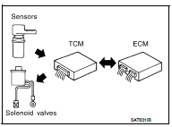
The TCM receives a signal from the vehicle speed sensor, transmission range switch and provides shift control or lock-up control via CVT solenoid valves.

The TCM also communicates with the ECM by means of a signal sent from sensing elements used with the OBD-related parts of the CVT system for malfunction-diagnostic purposes. The TCM is capable of diagnosing malfunctioning parts while the ECM can store malfunctions in its memory.

Input and output signals must always be correct and stable in the operation of the CVT system. The CVT system must be in good operating condition and be free of valve seizure, solenoid valve malfunction, etc.
It is much more difficult to diagnose an error that occurs intermittently

It is much more difficult to diagnose an error that occurs intermittently rather than continuously. Most intermittent errors are caused by poor electric connections or improper wiring. In this case, careful checking of suspected circuits may help prevent the replacement of good parts.

A visual check only may not find the cause of the errors. A road test with CONSULT-III (or GST) or a circuit tester connected should be performed. Follow the “DETAILED FLOW”.
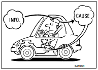
Before undertaking actual checks, take a few minutes to talk with a

Before undertaking actual checks, take a few minutes to talk with a customer who approaches with a driveability complaint. The customer can supply good information about such errors, especially intermittent ones. Find out what symptoms are present and under what conditions they occur. A “Diagnostic Work Sheet” as shown on the example (Refer to TM-176) should be used.

Start your diagnosis by looking for “conventional” errors first. This will help troubleshoot driveability errors on an electronically controlled engine vehicle.

Also check related Service bulletins.
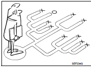
DETAILED FLOW

DETAILED FLOW

1.COLLECT THE INFORMATION FROM THE CUSTOMER

Get the detailed information from the customer about the symptom (the condition and the environment when the incident/malfunction occurred) using diagnosis worksheet. Refer to TM-176, "Diagnostic Work Sheet".

>> GO TO 2.

2.CHECK SYMPTOM 1

Check the following items based on the information obtained from the customer.

• Fail-safe. Refer to TM-169, "Fail-safe". • CVT fluid inspection. Refer to TM-184, "Inspection". • Line pressure test. Refer to TM-188, "Inspection and Judgment".

• Stall test. Refer to TM-186, "Inspection and Judgment".

>> GO TO 3.

3.CHECK DTC 1. Check DTC.

2. Perform the following procedure if DTC is detected.

• Record DTC.

• Erase DTC. Refer to TM-157, "Diagnosis Description".

Is any DTC detected? YES >> GO TO 4.

NO >> GO TO 5.

4.PERFORM DIAGNOSTIC PROCEDURE

Perform “Diagnostic Procedure” for the displayed DTC.

>> GO TO 5.

5.PERFORM DTC CONFIRMATION PROCEDURE

Perform “DTC CONFIRMATIOM PROCEDURE” for the displayed DTC.

Is DTC detected? YES >> GO TO 4.

NO >> GO TO 6.

6.CHECK SYMPTOM 2

Confirm the symptom described by the customer.

Is any malfunction present? YES >> GO TO 7.

NO >> INSPECTION END

7.RODE TEST

Perform “RODE TEST”. Refer to TM-190, "Description".

>> GO TO 8.

8.CHECK SYMPTOM 3

Confirm the symptom described by the customer.

Is any malfunction present? YES >> GO TO 2.

NO >> INSPECTION END

Diagnostic Work

INFORMATION FROM CUSTOMER

KEY POINTS

• WHAT..... Vehicle & CVT model • WHEN..... Date, Frequencies • WHERE..... Road conditions • HOW..... Operating conditions, Symptoms


DIAGNOSTIC WORKSHEET
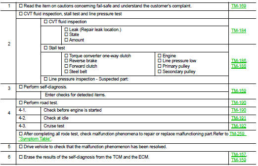
DIAGNOSTIC WORKSHEET

Additional service when replacing TCM