Exhaust manifold
Exploded View

1. Stud bolt
2. Exhaust manifold cover 3. Exhaust manifold
4. Gasket
 Engine front
 : N·m (kg-m, ft-lb)
 : N·m (kg-m, in-lb)
 : Always replace after every
disassembly.
Removal and Installation
REMOVAL
1. Drain engine coolant. Refer to CO-11, "Draining". 2. Remove turbocharger. Refer to EM-36, "Exploded View". 3. Remove catalyst convertor. Refer to EM-33, "2WD : Exploded View" (2WD models) or EM-34, "4WD : Exploded View" (4WD models). 4. Remove exhaust manifold cover.5. Remove exhaust manifold.
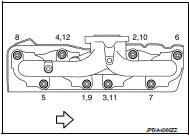
• Loosen nuts in reverse order as shown in the figure.
 : Engine front
NOTE:
Disregard the numerical order No. 9 to 12 in removal.

6. Remove gasket.
CAUTION:Cover engine openings to avoid entry of foreign materials.
INSTALLATION
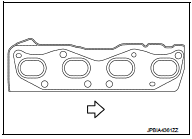
1. Install gasket to cylinder head as shown in the figure.
: Engine front
2. Install exhaust manifold with the following procedure: a. Tighten nuts in numerical order as shown in the figure.
: Engine front
NOTE: • Tighten nuts the No.1 to No.4 in two steps.
• The numerical order No.9 to No.12 shows the second step.
3. Install remaining parts in the reverse order of removal.
Inspection
INSPECTION AFTER REMOVAL
Surface Distortion
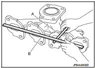
• Using feeler gauge (A) and straightedge (B), check the surface distortion of exhaust manifold mating surface in each exhaust port and entire part.
Limit : Refer to EM-130, "Exhaust Manifold".
• If it exceeds the limit, replace exhaust manifold.