Engine Mechanical MR16DDT

Intake manifold

In this manual: Engine Mechanical MR16DDT
Foreword — 1General information — 45Engine Mechanical MR16DDT — 61Engine Mechanical HR16DE — 52Engine Mechanical K9K — 46Engine Lubrication System MR16DDT — 18Engine Lubrication System HR16DE — 14Engine Lubrication System K9K — 11Engine Cooling System MR16DDT — 28Engine Cooling System HR16DE — 29Engine Cooling System K9K — 24Engine Control System MR16DDT — 163Engine Control System HR16DE — 115Engine Control System K9K — 129Fuel System MR16DDT — 13Fuel system HR16DE — 11Fuel system K9K — 12Exhaust system MR16DDT — 7Exhaust system HR16DE — 10Exhaust system K9K — 7Starting system — 24Accelerator control system — 6Clutch — 25Driveline transfer: TY21B — 77Driveline rear propeller Shaft: 3Fφ16-ETJ75 — 12Driveline rear final drive: RTVS — 31Transaxle & transmission 5MT: RS5F92R — 31Transaxle & transmission 6MT: RS6F94R — 30Transaxle & transmission CVT: RE0F10B — 93Transaxle & transmissioN CVT: RE0F11A — 103Front Axle MR16DDT — 18Front Axle HR16DE — 17Front Axle K9K — 17Rear Axle 2WD — 6Rear Axle 4WD — 13Front Suspension — 21Rear Suspension 2WD — 13Rear Suspension 4WD — 17Road Wheels & Tires — 6Brake System LHD — 24Brake System RHD — 24Parking Brake System — 8Brake Control System without ESP — 44Brake Control System with ESP — 63Steering System — 14Steering Control System — 27Seat Belt — 8SRS Airbag — 24SRS Airbag Control System — 93Ventilation System — 11Heater & Air Conditioning System HR16DE — 28Heater & Air Conditioning System MR16DDT — 28Heater & Air Conditioning Control System Type 1 — 49Heater & Air Conditioning Control System Type 2 — 51Heater & Air Conditioning Control System Type 3 — 32Heater & Air Conditioning Control System Type 4 — 40Heater & Air Conditioning Control System Type 5 — 21Interior — 16Instrument Panel — 10Seat — 18Door & Lock Type 1 — 83Door & Lock type 2 — 80Door & Lock type 3 — 65Door & Lock type 4 — 60Security Control System with intelligent key system — 82Security Control System without intelligent key system — 41Glass & Window System — 15Power Window Control System — 28Body Repair — 13Exterior — 20Mirrors — 26Exterior Lighting System Halogen type — 51Interior Lighting System — 24Wiper & Washer — 45Defogger — 31Horn — 4Power Outlet — 4Body Control System With intelligent key system — 21Body Control System Without intelligent key system — 23LAN system can fundamental — 6LAN system can — 31LAN System can system (type 1) — 1LAN System can system (type 2) — 1LAN System can system (type 3) — 1LAN System can system (type 4) — 1LAN System can system (type 5) — 1LAN System can system (type 6) — 1LAN System can system (type 7) — 2LAN System can system (type 8) — 1LAN System can system (type 9) — 1LAN System can system (type 10) — 1LAN System can system (type 11) — 1Power Control System IPDM E/R (with I-key) — 14Power Control System IPDM E/R (without I-key) — 14Power Control System Power distribution system — 25Charging System — 22Power Supply, Ground & Circuit Elements — 20Meter, Warning Lamp & Indicator — 33Warning Chime System — 22Audio, Visual & Navigation System Audio without navigation — 30Audio, Visual & Navigation System Audio with navigation — 33Audio, Visual & Navigation System NISSAN dynamic control system — 22Cruise Control System — 1Drive Mode System — 10Maintenance — 14
~3min read

Exploded View

1. Clamp

1. Clamp
2. Water hose
3. PCV hose
4. Clamp
5. Gasket
6. Intake manifold
7. Clamp
8. Vacuum hose
9. Vacuum gallery assembly 10. Clamp
11. EVAP hose
12. EVAP service port valve 13. EVAP hose
14.EVAP canister purge volume control solenoid valve
15. Bracket
16. Clamp
17. Bracket
18. EVAP hose
19. Clamp
20. EVAP tube
21. EVAP hose
22. Clamp
23. Clamp
24. Water hose
25. Electric throttle control actuator 26. Gasket

A. To turbocharger B. To centralized under-floor piping C. To recirculation valve hose

: N·m (kg-m, in-lb): N·m (kg-m, ft-lb)
: Always replace after every: N·m (kg-m, in-lb)
disassembly: Always replace after every
disassembly

Removal and Installation

REMOVAL

1. Remove engine cover. Refer to EM-25, "Exploded View".

2. Pull out oil level gauge.

CAUTION:
Cover the oil level gauge guide openings to avoid entry of foreign materials. 3. Disconnect turbocharger boost sensor (with intake air temperature sensor 2) harness connector. Refer to EM-31, "Exploded View". 4. Remove air inlet tube assembly. Refer to EM-31, "Exploded View".

5. Disconnect water hoses from electric throttle control actuator as follows: • Attach plug to prevent engine coolant leakage when engine coolant is not drained. Refer to CO-11, "Draining".

CAUTION:
Perform this step when the engine is cold.
NOTE:
This step is not required when removing only intake manifold.
6. Disconnect electric throttle control actuator harness connector.

7. Remove electric throttle control actuator.

CAUTION:
• Handle carefully to avoid any shock to electric throttle control actuator.

• Never disassemble electric throttle control actuator.

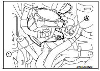
8. Disconnect EVAP canister purge volume control solenoid valve harness connector, and them remove bracket with EVAP canister purge volume control solenoid valve. 9. Remove vacuum gallery. 10. Disconnect PCV hose (intake manifold side). 11. Remove intake manifold (1) with the following procedure.

• Loosen and remove intake manifold mounting bolt (A).
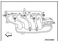
• Loosen mounting bolts in reverse order as shown in the figure.

• Loosen mounting bolts in reverse order as shown in the figure.

NOTE:: Engine front


NOTE:
Disregard the numerical order No.6 in removal.
CAUTION:
Cover engine openings to avoid entry of foreign materials.
INSTALLATION

INSTALLATION

Note the following, and install in the reverse order of removal.

Intake Manifold
1. Check if gasket is not dropped from the installation groove of intake manifold.

2. Install intake manifold with the following procedure:

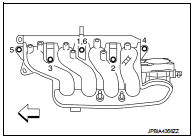
a. Tighten in numerical order as shown in the figure.

NOTE:: Engine front


NOTE:
• Tighten bolt the No.1 in two steps.

• The numerical order No.6 shows the second step.
3. Install in the reverse order of removal after this step.

3. Install in the reverse order of removal after this step.

Electric Throttle Control Actuator • Tighten bolts of electric throttle control actuator equally and diagonally in several steps. • Perform “Throttle Valve Closed Position Learning” after repair when removing harness connector of the electric throttle control actuator. Refer to EC-135, "Work Procedure".

• Perform “Throttle Valve Closed Position Learning” and “Idle Air Volume Learning” after repair when replacing electric throttle control actuator. Refer to EC-135, "Work Procedure" and EC-136, "Work Procedure".