Electric Controlled Coupling
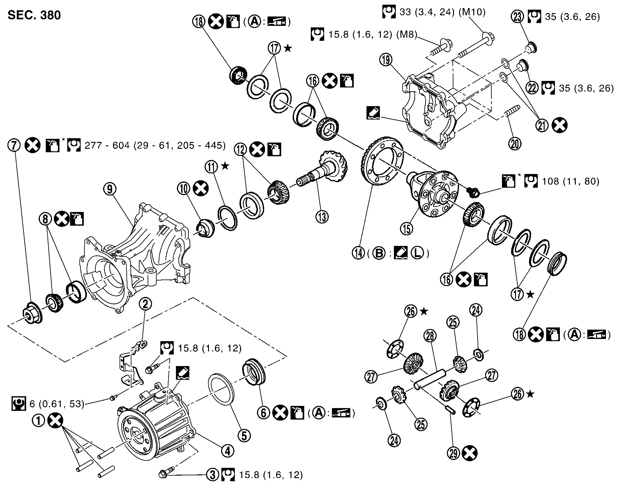
 |
Stud bolt |  |
Connector bracket |  |
Reamer bolt |
 |
Electric controlled coupling assembly |  |
Wave spring |  |
Drive pinion oil seal |
 |
Drive pinion lock nut |  |
Pinion front bearing |  |
Gear carrier |
 |
Collapsible spacer |  |
Drive pinion adjusting shim |  |
Pinion rear bearing |
 |
Drive pinion |  |
Drive gear |  |
Differential case |
 |
Side bearing |  |
Side bearing adjusting shim |  |
Side oil seal |
 |
Rear cover |  |
Stud bolt |  |
Gasket |
 |
Drain plug |  |
Filler plug |  |
Pinion mate thrust washer |
 |
Pinion mate gear |  |
Side gear thrust washer |  |
Side gear |
 |
Pinion mate shaft |  |
Lock pin | ||
 |
Oil seal lip |  |
Screw hole | ||
 : N·m (kg-m, in-lb) |
|||||
 : N·m (kg-m, ft-lb) |
|||||
 : Always replace after every disassembly. |
|||||
 : Select with proper thickness. |
|||||
 : Apply gear oil. |
|||||
| *: Apply anti-corrosion oil. |
|||||
 : Apply multi purpose grease. |
|||||
 : Apply Genuine Silicone RTV or equivalent. Refer to Recommended Chemical Products and Sealants. |
|||||
 : Apply Genuine High Strength Thread Locking Sealant or equivalent. Refer to Recommended Chemical Products and Sealants. |
|||||
DISASSEMBLY
Remove stud bolts .
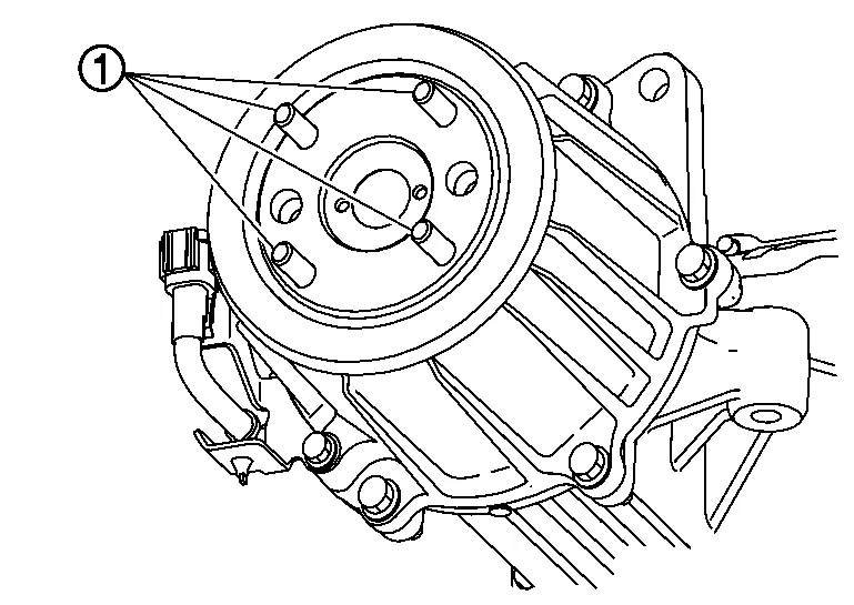
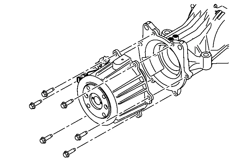
Remove electric controlled coupling assembly from final drive assembly.
Remove wave spring.
Remove drive pinion oil seal from the inside of gear carrier. Refer to Disassembly and Assembly.
Remove connector bracket from electric controlled coupling.
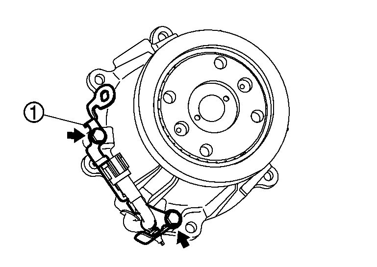
Separate connector clip from connector bracket.

ASSEMBLY
Install connector bracket to electric controlled coupling.
For tightening torque, refer to Exploded View.
Join AWD solenoid harness with connector clip.
Install drive pinion oil seal to the inside of gear carrier. Refer to Disassembly and Assembly.
Install wave spring to the inside of gear carrier.

Apply liquid gasket to mating surface of electric controlled coupling assembly.

For applying liquid gasket, refer to Exploded View.
Match electric controlled coupling assembly to spline of drive pinion, then install it to final drive assembly .
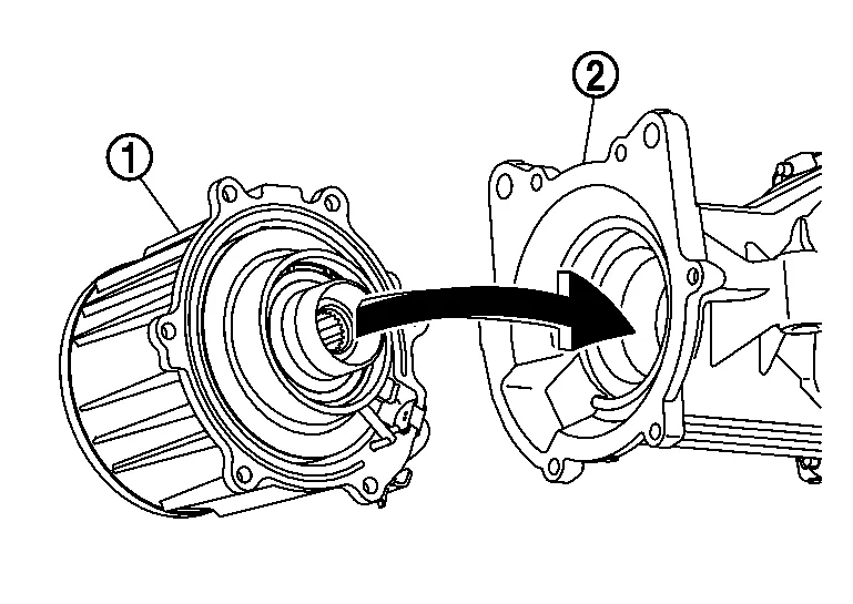
Temporarily tighten reamer bolts to the positions shown in the figure.
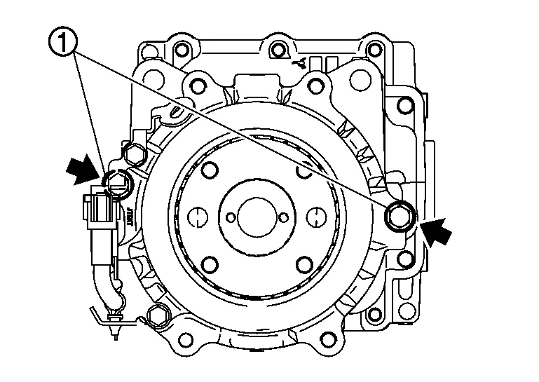
Tighten reamer bolts and electric controlled coupling assembly mounting bolts to the specified torque.
For tightening torque, refer to Exploded View.
Install stud bolts .

 |
: Electric controlled coupling side |
| Thread length | |
| A | : Long |
| B | : Short |