Turn Signal Lamp Circuit
CHECK TURN SIGNAL LAMP
 CONSULT
Select "FLASHER" in “Active Test” mode of “BCM(FLASHER)”.
While operating the test items, check that the turn signal lamp blinks.
LH : Turn signal lamp LH blinking RH : Turn signal lamp RH blinking OFF : The turn signal lamp OFF
Is the inspection result normal?
YES>>Turn signal lamp circuit is normal.
NO>>Refer to Diagnosis Procedure.
CHECK TURN SIGNAL LAMP OUTPUT VOLTAGE
Ignition switch OFF.
Disconnect the front combination lamp connector, door mirror connector and the rear combination lamp (body side) connector.
Ignition switch ON.
With turn signal switch operating, check the voltage between the front combination lamp harness connector and ground.
(+) (−) Voltage
(Approx.)Front combination lamp Connector Terminal LH E247 8 Ground 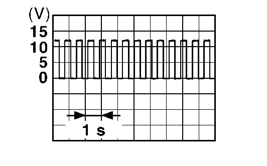
RH E243 With turn signal switch operating, check the voltage between the door mirror harness connector and ground.
(+) (−) Voltage
(Approx.)Door mirror Connector Terminal LH D4 20 Ground RH D107 With turn signal switch operating, check the voltage between the rear combination lamp (body side) harness connector and ground.
(+) (−) Voltage
(Approx.)Rear combination lamp (body side) Connector Terminal LH B460 8 Ground RH B459
Is the inspection result normal?
YES>>GO TO 3.
NO>>GO TO 2.
CHECK TURN SIGNAL LAMP POWER SUPPLY CIRCUIT
Ignition switch OFF.
Disconnect BCM connector.
Check continuity between the BCM harness connector and the front combination lamp connector.
Front combination lamp BCM Continuity Connector Terminal Connector Terminal LH E247 8 M80 117 Yes RH E243 105 Check continuity between the BCM harness connector and the door mirror connector.
Door mirror BCM Continuity Connector Terminal Connector Terminal LH D4 20 M20 98 Yes RH D107 104 Check continuity between the BCM harness connector and the rear combination lamp (body side) connector.
Rear combination lamp (body side) BCM Continuity Connector Terminal Connector Terminal LH B460 8 M20 103 Yes RH B459 92
Is the inspection result normal?
YES>>Replace BCM. Refer to Removal and Installation.
NO>>Repair the harness or connector.
CHECK TURN SIGNAL LAMP GROUND CIRCUIT
Check continuity between the front combination lamp harness connector and ground.
Front combination lamp — Continuity Connector Terminal LH E247 7 Ground Yes RH E243 Check continuity between the door mirror harness connector and ground.
Door mirror — Continuity Connector Terminal LH D4 21 Ground Yes RH D107 Check continuity between the rear combination lamp (body side) harness connector and ground.
Rear combination lamp (body side) — Continuity Connector Terminal LH B460 7 Ground Yes RH B459
Is the inspection result normal?
YES>>Replace the malfunctioning lamp.
NO>>Repair the harness or connector.