Wheel Side
REMOVAL
Remove disc brake rotor. Refer to Removal and Installation.
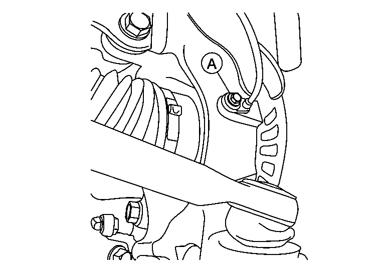
Remove wheel sensor bolt (A) and position wheel sensor aside. Refer to Exploded View.
Remove cotter pin.
Remove nut retainer.
Loosen wheel hub lock nut from drive shaft using power tool.
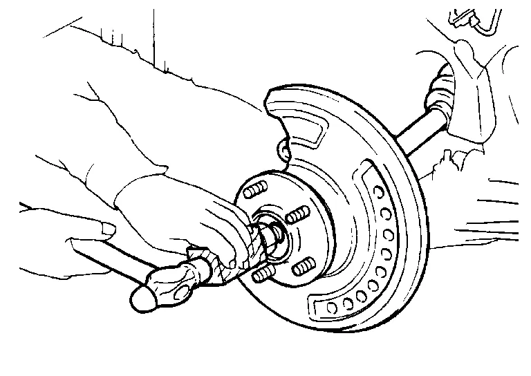
Using a piece of wood and a suitable tool, tap on wheel hub lock nut to disengage drive shaft from wheel hub and bearing.
Remove wheel hub lock nut.
Remove lower strut bolts and nuts.
Separate front strut from steering knuckle. Refer to Exploded View.
Separate drive shaft from front wheel hub and bearing.
Remove boot bands, and then separate boot from joint sub-assembly.
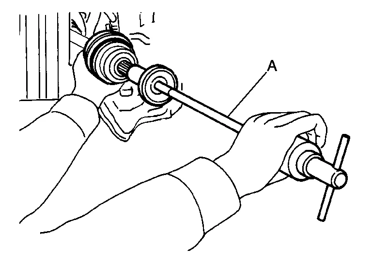
Screw suitable tool (A) 30 mm (1.18 in) or more into threaded part of joint sub-assembly. Support drive shaft with one hand and pull out joint sub-assembly from housing with suitable tool.
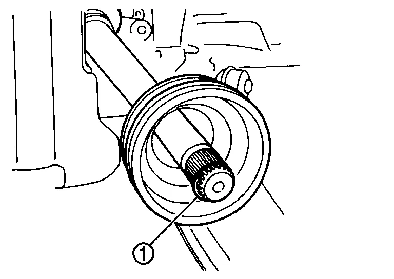
Remove circular clip (1) from shaft.
Remove boot from shaft.
While rotating ball cage, clean old grease off joint sub-assembly.
INSPECTION AFTER REMOVAL
Move joint up/down, left/right, and in axial directions. Check for motion that is not smooth and for significant looseness.
Check boot for cracks, damage, and leakage of grease.
INSTALLATION
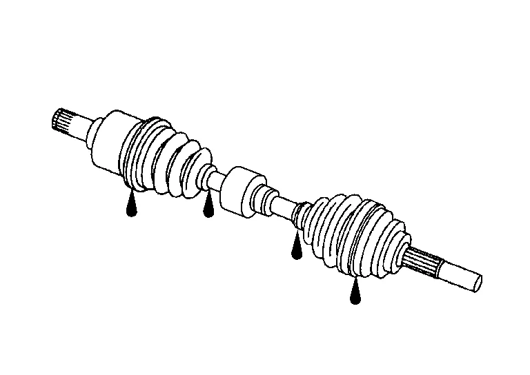
Insert Genuine NISSAN Grease into joint sub-assembly serration hole until grease begins to ooze from ball groove and serration hole.
Install new boot and new small boot band on shaft.
Remove protective tape wrapped around serrated part of shaft.
Attach new circular clip to shaft. Circular clip must fit securely into shaft groove.
Align shaft and joint sub-assembly. Assemble shaft with joint sub-assembly while holding circular clip.
Install joint sub-assembly (1) to shaft using suitable tool.
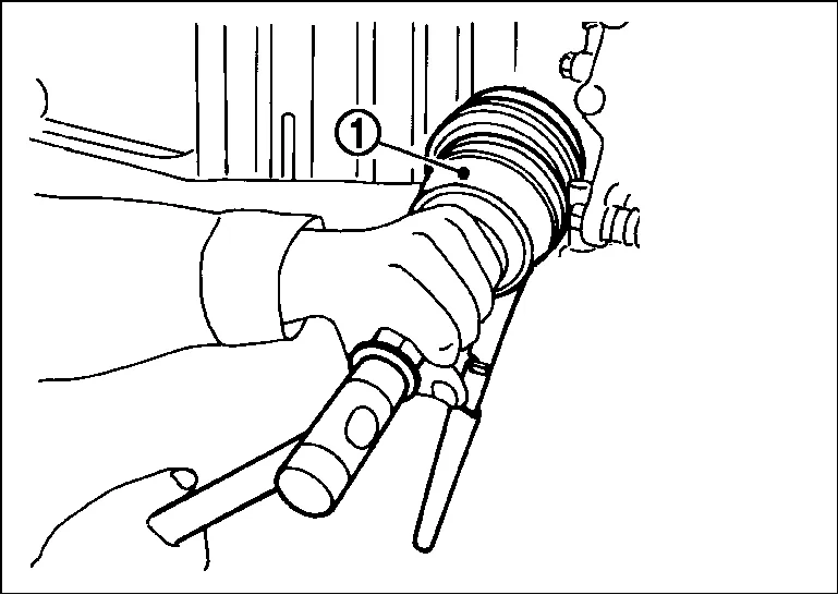
Pull the joint sub-assembly in the axial direction away from transaxle assembly. Confirm that the joint sub assembly cannot be pulled out.
Apply specified amount of Genuine NISSAN Grease into large diameter side opening of boot.
| Grease amount | : Refer to Drive Shaft. |
Install boot securely into grooves (indicated by “*” marks) as shown.
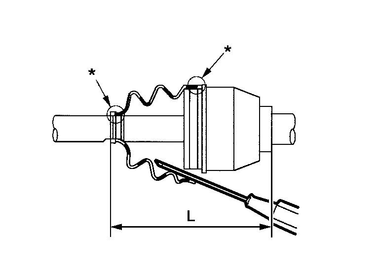
Make sure boot installation length (L) is specified length. Insert a suitable tool into the large end of boot. Bleed air from boot to prevent boot deformation.
| Boot installation length (L) | : Refer to Drive Shaft. |
Install new large and small boot bands securely using Tool.
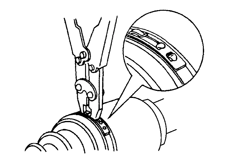
| Tool number | : KV40107300 (J-51751) |
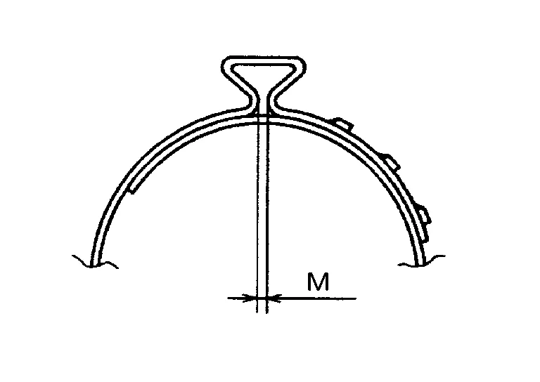
| Dimension (M) | : Refer to Boot Bands. |
Attempt to rotate boot to check whether or not boot bands are securing boot. If boot is not secure, remove boot bands, reposition boot, and install new boot bands.
Clean mating surface of wheel hub lock nut and wheel hub and bearing.
Clean mating surface of drive shaft (A) and wheel hub and bearing.
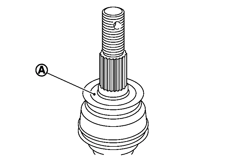
Insert drive shaft to wheel hub and bearing, and then temporarily tighten wheel hub lock nut.
Attach front strut to steering knuckle and tighten lower strut nuts to specification. Refer to Exploded View.
Tighten wheel hub lock nut to specified torque. Refer to Exploded View.
Install nut retainer (2) and a new cotter pin (1); securely bend cotter pin to prevent rattles.

Install front wheel sensor to steering knuckle. Refer to Exploded View.
Install disc brake rotor. Refer to Removal and Installation.
INSPECTION AND ADJUSTMENT AFTER INSTALLATION
Check wheel alignment. Refer to Inspection.
Adjust neutral position of the steering angle sensor. Refer to Description.