Alternator
IDENTIFICATION
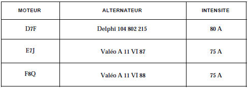
CHECKING
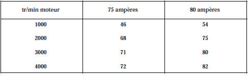
After 15 minutes of warm-up at 13.5 volts.
OPERATION - DIAGNOSIS
These vehicles are fitted with internally ventilated alternators with built-in regulator and a dashboard warning light, which operates as follows:
- when the ignition is switched on, the warning light comes on,
- when the engine starts, the warning light goes out,
- if the warning light comes back on while the engine is running, it indicates a “charge” fault.
FAULT FINDING
The warning light does not come on when the ignition is switched on
Check:
- the quality of the electrical connections,
- whether the bulb is blown (to check, earth the circuit; the bulb must light).
The warning light comes on with the engine running
It indicates a charging fault, which may be caused by:
- a broken alternator belt, a break in the charging cable,
- internal damage to the alternator (rotor, stator, diodes or brushes),
- a regulator fault,
- an overvoltage.
The customer complains of a charging fault and the warning light operates correctly.
If the regulated voltage is below 13.5 V, check the alternator. The fault may be due to:
- a destroyed diode,
- an open phase,
- carbon brush sticking or worn slip rings.
Voltage check
Connect a voltmeter across the battery terminals and read the battery voltage.
Start the engine and increase speed until the voltmeter needle stabilises at the regulated voltage.
This voltage must be between 13.5 V and 14.8 V.
Switch on as many electrical consumers as possible; the regulated voltage must remain between 13.5 V and 14.8 V.
WARNING: before any arc welding work on the vehicle, it is imperative to disconnect the battery and the regulator.
DIAGNOSIS
CHARGING CIRCUIT CHECK USING DIAGNOSTIC STATION
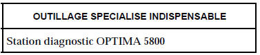
The OPTIMA 5800 diagnostic station checks the alternator by measuring the voltage and the output current, with and without electrical consumers.
NOTE: the station's current clamp is an inductive type (measuring range: 0 to 1,000 A). It is fitted without disconnecting the battery, which keeps the ECU memories and adaptive values intact.
Place the current clamp directly at the alternator output, with the clamp arrow pointing towards the alternator (the station detects incorrect positioning).
Measurements are carried out in three stages:
- battery voltage measurement with ignition off,
- regulation voltage and output current measurement without consumers,
- regulation voltage and output current measurement with as many consumers as possible.
At the end of the test, the values recorded lead, where applicable, to the following diagnostic messages:
- Battery voltage at no load < 12.3 V = battery discharged.
Without consumers:
- Regulation voltage > 14.8 V => faulty regulator,
- (regulation voltage at no load < 13.2 V) or (charging current < 2 A) => charging fault.
With consumers:
- Regulation voltage > 14.8 V => faulty regulator,
- Regulation voltage < 12.7 V => check the alternator output against its specifications:
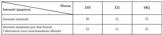
DIAGNOSIS (continued)
If the measured output is too low, check:
- alternator wear (brushes...),
- the battery connections,
- the engine earth strap,
- the alternator conformity,
- the belt tension.
If the measured output is correct but the regulation voltage is too low, the alternator is not at fault.
The cause is either:
- the vehicle has too many electrical consumers,
- the battery is discharged
D7F / E7J engines
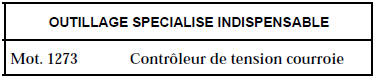
REMOVAL
Position the vehicle on a two-post lift.
Disconnect the battery and the alternator electrical connections.
Remove:
- the alternator belt and the power steering pump belt on D7F engine (if fitted),
- the alternator.
INSTALLATION
Refit in the reverse order of removal.
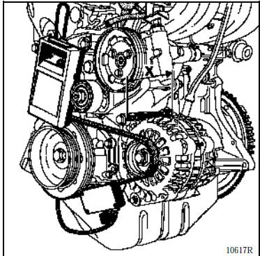
D7F engine
To tension the alternator belt, use the locally made tool below (100 mm threaded rod (X) and three M6 nuts).
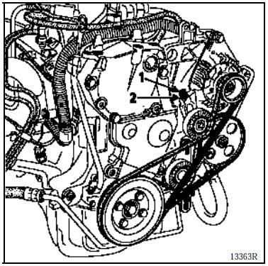
E7J Engine
Tension the belt using screw (1), then tighten nut (2) after measuring the tension.
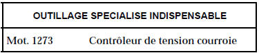
Refer to section 07 "Accessory belt tension" for tension values.
F8Q engine
REMOVAL
Position the vehicle on a two-post lift.
Disconnect the battery and the alternator electrical connections.
Remove:
- the right front wheel arch,
- the alternator mountings and the belt,
- the bracket (A),
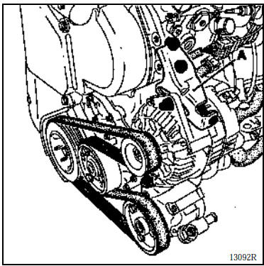
- the crossmember mounting bolts and move it aside to remove the alternator.
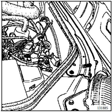
INSTALLATION
Refit in the reverse order of removal.
Refer to section 07 "Accessory belt tension" for tension values.
Test yourself
A quick Renault Kangoo quiz: every answer comes with an explanation and a link to the manual page.