Interpreting XR25 bar graphs

INSTRUCTIONS Check that the K and L lines are not disturbed by another ECU.
| Check the condition of the + AVC fuse. Replace the fuse if necessary. |
| Make sure the XR25 valise is not the cause of the fault by trying to communicate with another vehicle ECU (air conditioning ECU, injection ECU, etc.). Check that the ISO interface is set to S8, that you are using the latest XR25 cassette version and the correct access code (D 56). Check the battery voltage (U > 10.5 volts). Recharge the battery if necessary. |
| Check that the 18-way connector of the decoder box is fully clipped in. Check that the decoder box is correctly powered:
|
| Make sure the diagnostic socket is correctly powered. Check and ensure the continuity and insulation of the wiring on pins A3 and A4 of the decoder box connector. |
| If there is still no communication between the XR25 valise and the decoder box, replace the decoder box. |
AFTER REPAIR Once communication is established, deal with any fault bar graphs that are lit.
Carry out a conformity check.

WARNINGS None.
Using the XR25 valise, correctly reconfigure the decoder box.On the XR25 valise keypad, enter G22*1* for a petrol vehicle, G22*2* for a diesel vehicle.
NOTE: On diesel versions, an incorrect decoder box configuration does not prevent the immobiliser from working correctly. However, in the event of a fault, the immobiliser warning light will not come on.
AFTER REPAIR Erase the stored fault by entering G0** on the XR25 valise keypad.
Carry out a conformity check.
Check the operation of the immobiliser system.

INSTRUCTIONS Reminder: In normal operation:
bar graph 4D on with the ignition switch in the +APC position
bar graph 4D off with the ignition switch in any position other than +APC
| Check the +APC fuse. Replace the fuse if necessary. |
| Ignition on, check for the presence of +12 volts on pin A7 of the decoder box 18-way connector. Is there 12 volts? |
| YES | Replace the decoder box. |
| NO | Repair the wiring between pin A7 of the decoder box 18-way connector and the passenger compartment fuse board. |
AFTER REPAIR Carry out a conformity check.
Check the operation of the immobiliser system.

INSTRUCTIONS Check that the CPE switch is not permanently pressed due to a mechanical constraint.
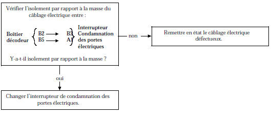
AFTER REPAIR Erase the stored fault by entering G0** on the XR25 valise keypad.
Carry out a conformity check.
Check the operation of the immobiliser system.

INSTRUCTIONS Check that the ECU configuration is correct:
diesel: right bar graph 3 on
petrol: right bar graph 3 off
| Set the XR25 valise to pulse detector mode ("G" key, input via the "Vin" terminal). Ignition on, check for pulses on pin A6 of the decoder box 18-way connector (test with the decoder box connector and the coded solenoid valve electronics connected). Ignition on, if there are no pulses, replace the decoder box. |
| Keep the ignition on for more than 30 consecutive seconds, then switch the ignition off and wait for the immobiliser warning light to flash (immobiliser active). Switch the ignition back on and check that bar graph 8 left stays permanently on. Is bar graph 8 left permanently on? |
| YES | Replace the decoder box. |
| NO | Replace the coded solenoid valve electronics. |
AFTER REPAIR Erase the stored fault by entering G0** on the XR25 valise keypad.
Carry out a conformity check.
Check the operation of the immobiliser system.

INSTRUCTIONS Before starting the diagnosis, keep the ignition on for more than 30 consecutive seconds, then switch the ignition off.
| On diesel versions, if bargraphs 6D and 6G are on, check the impact switch. |
| Make sure the connector of the coded solenoid valve electronics is properly connected. |
| Check the condition of the wiring between pin A6 of the decoder unit and pin 8 of the coded solenoid valve connector, and check the 12-volt supply and earth. Repair it if necessary. |
| Set the XR 25 tool to pulse detector mode ("G" key, input via the "Vin" terminal). Ignition on, check for pulses on pin A6 of the decoder unit connector (test with the decoder unit and coded solenoid valve electronics connectors connected). Are there pulses? |
| YES | Replace the electronic unit on the solenoid valve side. |
| NO | Replace the decoder box. |
AFTER REPAIR Erase the stored fault by entering G0** on the XR25 valise keypad.
Carry out a conformity check.
Check the operation of the immobiliser system.

WARNINGS None.
| On petrol versions, if bargraph 6D is on, check the impact switch. |
| Check the continuity and the insulation to earth and to 12 volts of the wiring between pin A6 of the 18-way decoder unit connector and pin ** of the injection computer. Repair the wiring if necessary. |
| Set the XR 25 tool to pulse detector mode ("G" key, input via the "Vin" terminal). Ignition on, check for pulses on pin A6 of the decoder unit connector (test with the decoder unit and injection computer connectors connected). Are there pulses? |
| YES | Replace the injection computer. |
| NO | Replace the decoder box. |
** pin: 43 or 19 depending on engine
AFTER REPAIR Erase the stored fault by entering G0** on the XR25 valise keypad.
Carry out a conformity check.
Check the operation of the immobiliser system.

WARNINGS None.
Check the continuity and the insulation to earth and to 12 volts of the wiring between: Repair the wiring if necessary. |
| Check that the receiver ring is supplied with earth on pin 2 and 12 volts on pin 3. |
| Ignition off, check for +12 volt voltage on pin A2 of the decoder unit connector on the wiring side (decoder connector disconnected and ring connector connected). If 12 volts +AVC is not measured, replace the +AVC fuse. If the problem persists, replace the receiver ring. |
| Disconnect the 4-way connector of the receiver ring. Set the XR25 valise to pulse detector mode ("G" key, input via the "Vin" terminal). Switching the ignition back on, check for a pulse on pin A2 of the 18-way decoder unit connector (test with the decoder unit and receiver ring connectors connected). When the ignition is switched on, is there a pulse? |
| YES | Replace the receiver ring. |
| NO | Replace the decoder box. |
AFTER REPAIR Erase the stored fault by entering G0** on the XR25 valise keypad.
Carry out a conformity check.
Check the operation of the immobiliser system.

NOTES If bargraph 17D is on, do not apply the following diagnosis because the decoder unit is blank. Perform the TIR key learning procedure.
Only consult the following diagnosis if bargraph 11G stays off after trying to lock or unlock the vehicle doors with the TIR.
| If bargraph 17D is on, do not apply the following diagnosis because the decoder unit is blank. Perform the TIR key learning procedure. Only consult the following diagnosis if bargraph 11G stays off after trying to lock or unlock the vehicle doors with the TIR. |
| Check the IR transmitter connector for +12 V AVC voltage between pins B2 and A3. Is this voltage present? |
| YES | Set the XR25 valise to pulse detector mode ("G" key, input via the "Vin" terminal). Check for pulses on pin B2 of the IR transmitter while pressing the TIR (test with the decoder unit and IR transmitter connectors connected). Are there pulses when the TIR is pressed? |
| YES Replace the decoder unit. | |
| NO Replace the IR transmitter. | |
| NO | Check the insulation to earth of the wiring between: Is there insulation to earth? |
| YES Repair the faulty wiring. | |
| NO Replace the decoder unit. |
AFTER REPAIR Carry out a conformity check.
Check the operation of the immobiliser system.

NOTES Only consult the following diagnosis if, when the TIR is pressed, bargraph 11G lights for 3 seconds and bargraph 11D stays off.
Check that the keys belong to the vehicle.
There is a desynchronisation between the TIR code and the decoder box code if, when the TIR is pressed, the right bar graph 11 stays off (while the left bar graph 11 lights for about 3 seconds before going off) and the vehicle doors cannot be locked or unlocked with the TIR.Apply the TIR resynchronisation procedure.
AFTER REPAIR Carry out a conformity check.
Check the operation of the immobiliser system.
Test yourself
A quick Renault Kangoo quiz: every answer comes with an explanation and a link to the manual page.