Fuel vapour recovery
D7F engine
CIRCUIT FUNCTIONAL DIAGRAM
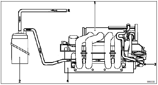
- Intake manifold
- Fuel vapour absorber (canister)
- RCO-controlled solenoid valve
- Cylinder head
R Line from the tank
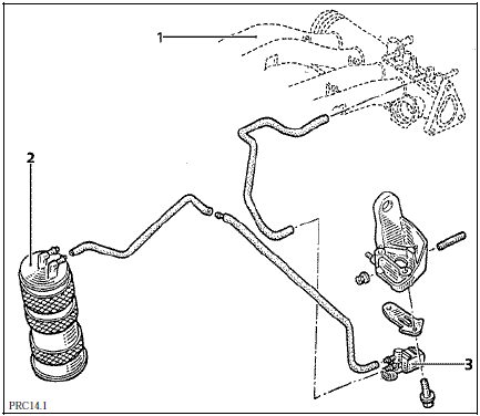
E7J Engine
CIRCUIT FUNCTIONAL DIAGRAM
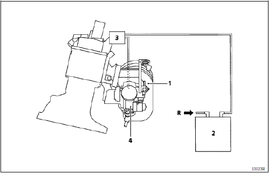
- Intake manifold
- Fuel vapour absorber (canister)
- RCO-controlled solenoid valve
- Throttle body
R Line from the tank
CANISTER PURGE CONDITIONS (E7J engine)
In mixture control
Coolant temperature above 50 °C.
Intake air temperature above 15 °C.
Accelerator released position not detected. (If the throttle position sensor fails, the 'accelerator released position not detected' condition is replaced by an engine speed condition of R > 1500 rpm.)
Not in mixture control
- Coolant temperature above 50 °C.
- Intake air temperature above 15 °C.
- Full-load position detected (depends on engine speed and manifold pressure).
If the oxygen sensor fails, purging is permitted without the accelerator released condition.
The canister purge solenoid valve duty cycle can be viewed with the XR25 tester at #23. The valve is closed at #23 = 0.7% (minimum value).
CANISTER PURGE CONDITIONS (D7F engine)
- Coolant temperature above +15 °C
- Intake air temperature above +10 °C.
- Accelerator released position not detected. (If the throttle position sensor fails, the 'accelerator released position not detected' condition is replaced by an engine speed condition of R > 1500 rpm.)
The canister purge solenoid valve duty cycle can be viewed with the XR25 tester at #23. The valve is closed at #23 = 0.7%.
CHECKING CANISTER PURGE OPERATION
A fault in the system can cause unstable idle or engine stalling.
Check the circuit against the functional diagrams.
Make sure the hose marked "CAN" on the solenoid valve is connected to the canister.
Check the condition of the hoses up to the tank.
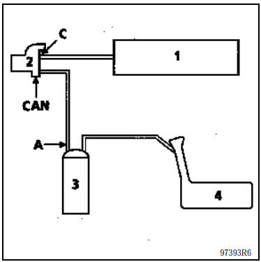
- Intake manifold
- Canister purge solenoid valve
- Canister
- Reservoir
At idle, connect a gauge (-3 to +3 bar) (Mot. 1311-01) to the "CAN" outlet of the solenoid valve and check that there is no vacuum. (In the same way, the command value read by the XR25 tester at #23 must remain at its minimum, X = 0.7%.)
Is there a vacuum?
YES Ignition off. Using a vacuum pump, apply a vacuum of 500 mbar to the solenoid valve at (C). It must not vary by more than 10 mbar in 30 seconds.
Does the pressure vary? YES The solenoid valve is faulty; replace it. In addition, blow through the hose (A) connecting the valve to the canister to remove any activated charcoal fragments.
NO There is an electrical fault; check the circuit.
NO In purge conditions (not at idle, engine warm), a rise in vacuum must be observed. (At the same time, the #23 value on the XR25 must increase.)
LOCATION - REMOVAL
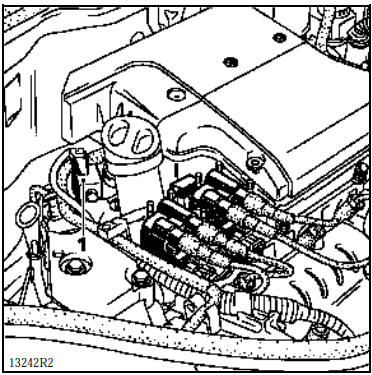
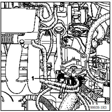
CANISTER PURGE SOLENOID VALVE (1)
E7J Engine
It is mounted above the intake manifold, under the trim cover.
D7F engine
It is mounted at the front on the lifting bracket.
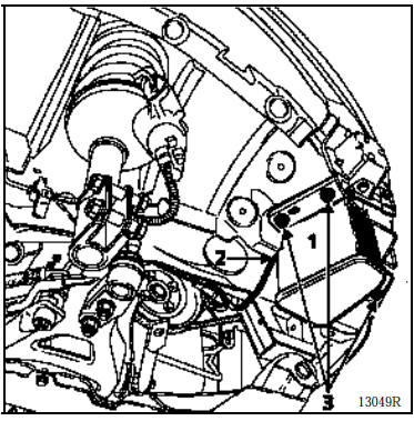
REMOVAL OF THE FUEL VAPOUR ABSORBER (1)
It is located in the front right wheel arch.
REMOVAL
Disconnect the canister-to-manifold hose from the top of the vehicle.
From underneath, remove the wheel arch liner.
Disconnect the canister-to-tank hose (2).
Remove the three bolts (3) securing the canister (1), then remove it.
Test yourself
A quick Renault Kangoo quiz: every answer comes with an explanation and a link to the manual page.