Sill
Replacing this part is a basic operation for a side collision.
In the method described below, you will only find the descriptions and joins specific to the part concerned.
Information on related parts is covered in their respective sections (see contents).
To carry out this operation, order the inflatable inserts corresponding to each replacement case below.
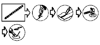
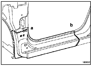
The replacement is carried out by combining cuts (a, b and c).
The cut positions given in this method may vary depending on the severity of the impact.
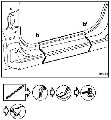
Note: If the spot welds cannot be made with the spot cutter, they can be replaced with plug welds.For a front rocker panel replacement, cut (b) must be made twice in zone X1 (see example at the end).
REPLACEMENT PART CONTENTS
Part supplied assembled with:
Welded stud
Rear jack support
Front jack support
5-door version
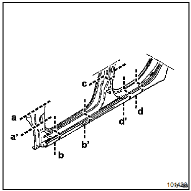
3-door version
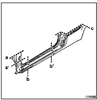
PARTS CONCERNED (thickness in mm):
- Sill 0.9
- Front jack support 1.8
- Rear jack support 1.8
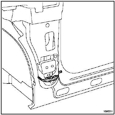
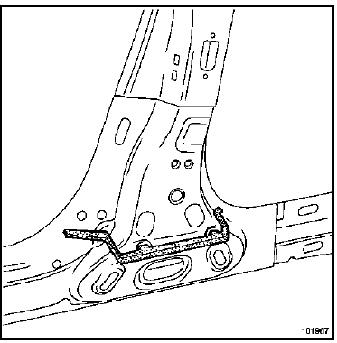
DETAIL OF INFLATABLE INSERT POSITIONS
Front pillar, 3- and 5-door versions
Centre pillar, 5-door version
Rear wing panel, 3-door version
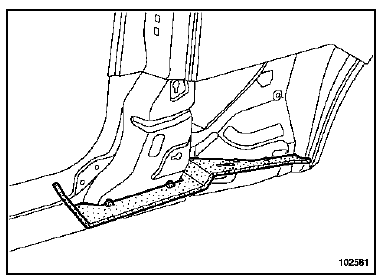
Detail of cut on front pillar, 3- and 5-door versions
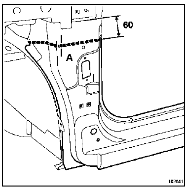
Upper cut (a).
WARNINGBeyond this limit, the replacement part will no longer overlap correctly.
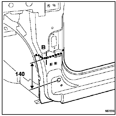
Lower cut (a').
Note: It is not recommended to make cut (a') below this limit, to avoid cutting into the inflatable insert.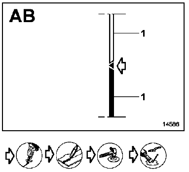
Detail of cut on rocker panel, 5-door version
Note: In the event of a very localised impact, a partial replacement can be carried out in zone X1.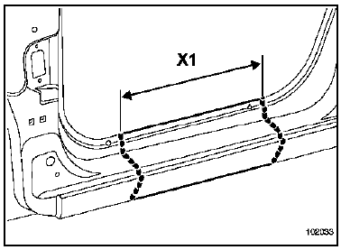
This method can also be applied to the rear side rocker panel.
Cut (b) is made in front of the jack support.
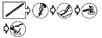
Detail of cut on centre pillar, 3-door version
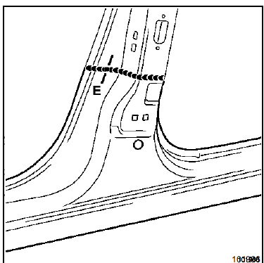
Do not make the cut below this limit, to avoid contaminating the inflatable insert.
When cutting, preserve the centre pillar reinforcement and the lining.
Detail of cut on wing panel, 3-door version
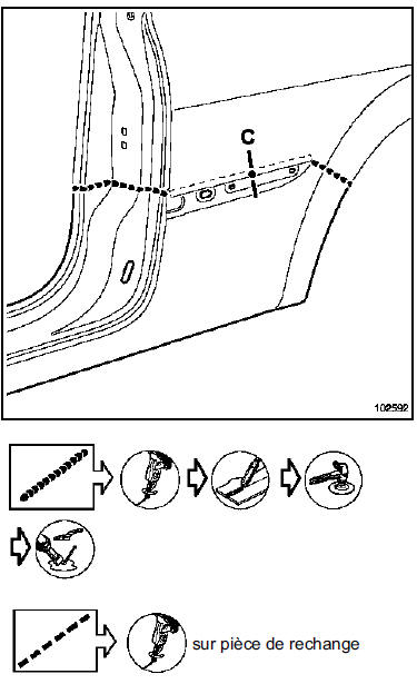
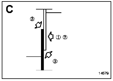
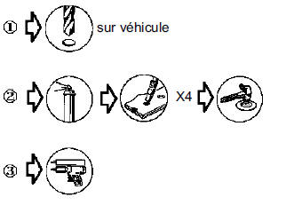
Detail of rear cut, 5-door version
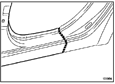
Avoid cutting beyond this limit so as not to affect the shock restraint housing and the inflatable insert.
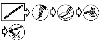
EXAMPLES OF CUT COMBINATIONS
Partial front replacement using cuts (a, b)
Partial front rocker panel replacement using cuts (b, b')
Partial rear replacement using cuts (b, c, d), 3-door version
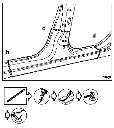
CAUTION When cutting, preserve the centre pillar reinforcement at (c).
STONE CHIP PROTECTION
Part description
The adhesive film is protected by a release sheet on the adhesive side.
INSTALLATION
Clean the entire bonding area with heptane using a lint-free cloth.
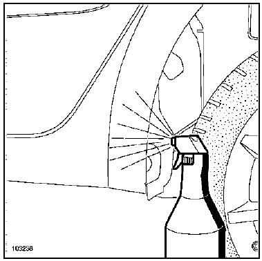
Spray water onto the bonding area.
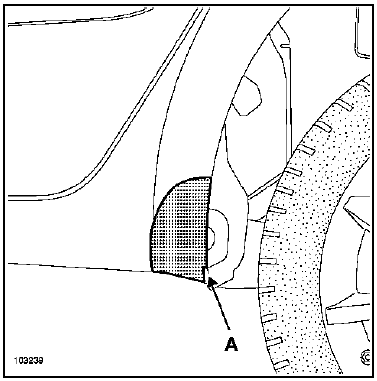
Carefully locate the notch of the adhesive film and the rear wing (A).
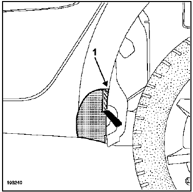
Partially remove the release sheet (adhesive side) from the rear part of the film (1).
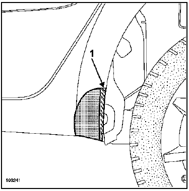
Position and bond the rear part of the film (1) to the rear edge of the rear wing.
IMPORTANT Do not touch the adhesive part of the film with your fingers.
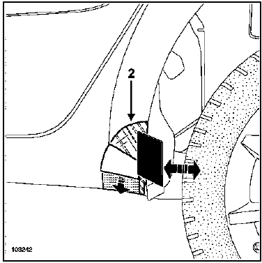
Using the squeegee, bond the film with a rear-to-front movement, taking care to avoid air bubbles.
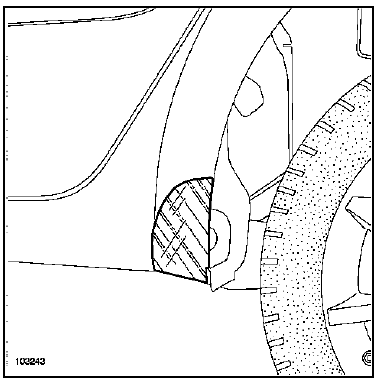
Hold the film vertically and bond the front part (2) to the bottom of the rear wing.
Test yourself
A quick Renault Megane quiz: every answer comes with an explanation and a link to the manual page.