Chassis
Hydraulic unit
In this manual: Chassis
~13min read
K4J, and 730 or 732
Essential equipment |
| charging station |
| pedal press |
| diagnostic tool |
Tightening torques |
|
| hydraulic unit mounting bolt on bracket | 0.8 daN.m |
| pipe mounting bolts on the hydraulic unit | 1.7 daN.m |
| hydraulic unit bracket to body bolts | 6.5 daN.m |
| air distributor mounting bolts | 0.9 daN.m |
| air conditioning pipe bolts | 0.8 daN.m |
| BA cover bolts | 0.4 daN.m |

REMOVAL
- Disconnect the battery, starting with the negative terminal.
AIR CONDITIONING or AUTOMATIC AIR CONDITIONING
- Remove:
- the front right wheel,
- the right-hand front mudguard,
- the undershield.
- Drain the refrigerant circuit using the charging station tool.
- Fit the brake pedal depressor tool on the brake pedal to limit brake fluid flow.
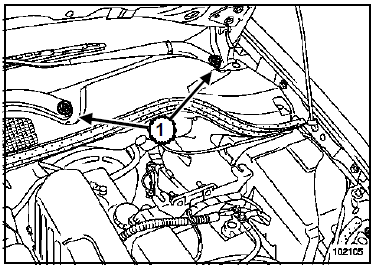
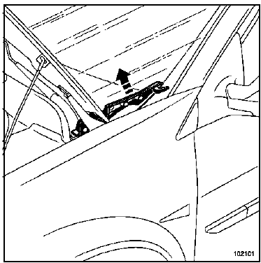
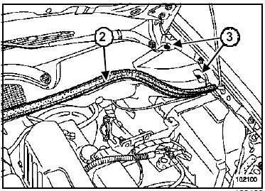
- Remove:
- the engine covers,
- the wiper arm nuts (1),
- the wiper arms,
- the left and right pillars,
- the bulkhead seal (2),
- the plastic rivets (3),
- the cowl grille,
- the water box partition.
- Remove:
- the air resonator housing mounting bolt (4),
- the air resonator housing (5).
Do not damage the vacuum outlet on the air distributor. Damage requires replacement of the air distributor.
- Disconnect:
- the brake booster vacuum hose on the air distributor side,
- the ignition coil connectors,
- the throttle body connector.
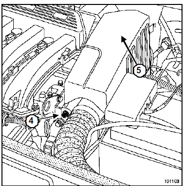
- Disconnect the air temperature sensor (6).
- Unclip the harness from the engine (7).
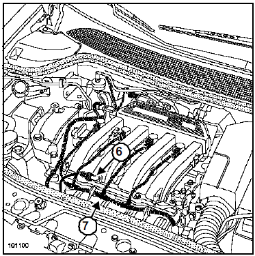
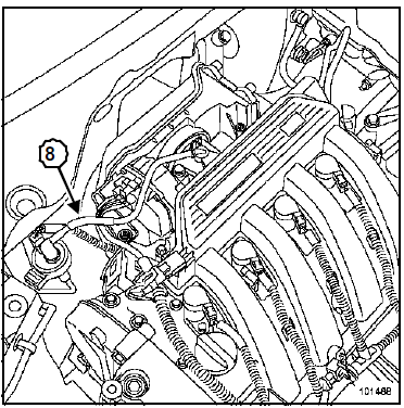
- Unclip the fuel vapour recirculation hose (8).
- Unscrew the air filter housing mountings, without removing it from the engine compartment.
- Remove:
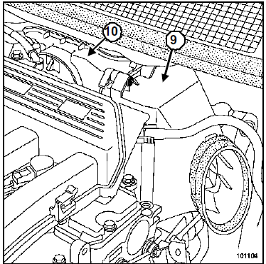
- the filter element (9),
- the air filter housing (10),
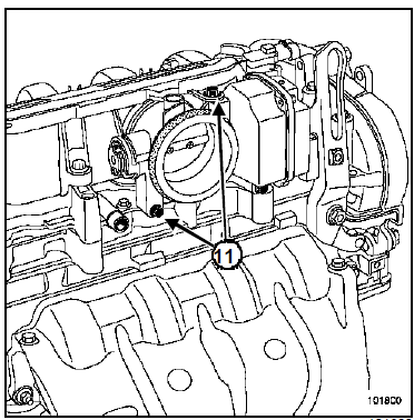
- the throttle body mounting bolts (11),
- the throttle body.
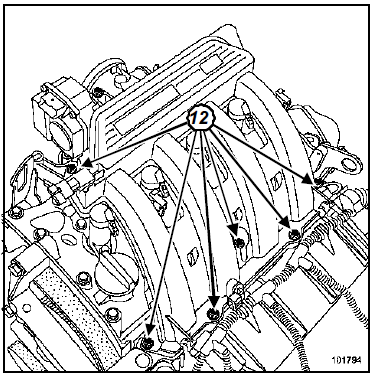
- Remove:
- the air distributor housing mounting bolts (12),
- the air distributor housing,
- the heat shield mountings.
- Remove the heat shield.
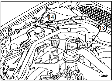
- Remove:
- the lifting eye (13),
- the air conditioning pipe flange bolt on the bulkhead side,
- the air conditioning pipe flange bolt on the receiver/drier side,
- the air conditioning pipe (14) between the bulkhead flange and the receiver/drier (if fitted).
- Remove:
- the condensate drain channel (15),
- the ABS ECU earth terminal mounting bolt (17).
- Disconnect the ECU connector.
- Unscrew the six pipes from the hydraulic unit.
- Unclip the six pipes from the hydraulic unit.
- Remove
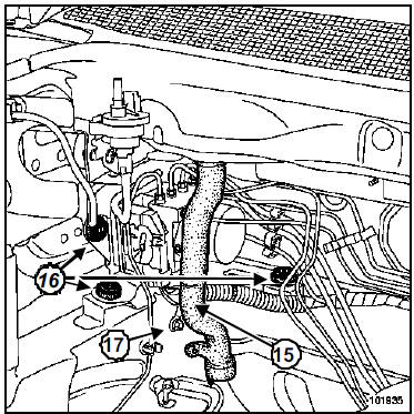
- the hydraulic unit bracket mounting bolts (16),
- the "hydraulic unit bracket - hydraulic unit" assembly,
- the hydraulic unit to bracket mounting bolts,
- the hydraulic unit.
INSTALLATION
- Refit in the reverse order of removal.
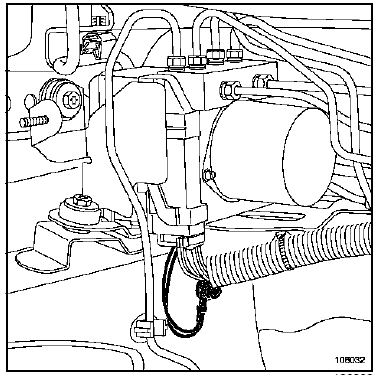
Position the earth terminal with the wires facing down to optimise the seal of the hydraulic unit ECU connector.
- Tighten to the following torques:
- the hydraulic unit to bracket mounting bolts (0.8 daN.m),
- the pipe mounting bolts on the hydraulic unit (1.7 daN.m),
- the hydraulic unit bracket to body bolts (6.5 daN.m),
- the air distributor mounting bolts (0.9 daN.m).
AIR CONDITIONING or AUTOMATIC AIR CONDITIONING
Tighten the air conditioning pipe bolts to torque (0.8 daN.m).
WARNING- Always replace the throttle body seal when it is removed. When the ignition is switched on, the throttle body must carry out a learning cycle for the minimum and maximum stops. Use the diagnostic tool to check that this learning has been carried out correctly.
- Always replace the seals at the ends of the air conditioning pipe with new seals.
- Connect the battery; carry out the necessary relearn procedures (see Battery chapter).
- Bleed the brake circuit using the diagnostic tool (see General, Bleeding the brake circuit, page 30A-5).
AIR CONDITIONING or AUTOMATIC AIR CONDITIONING
- Refill the refrigerant circuit using the charging station tool.
- Check the air conditioning operates correctly with the fan unit at maximum speed.
- If there is no cooling, carry out a leak check (see Leak Detection).
- Torque the battery cover screws (0.4 daN.m).
K4M, and 760 or 761
Essential equipment |
| charging station |
| pedal press |
| diagnostic tool |
Tightening torques |
|
| hydraulic unit to its bracket mounting bolts | 0.8 daN.m |
| pipe mounting bolts on the hydraulic unit | 1.7 daN.m |
| hydraulic unit bracket to body bolts | 6.5 daN.m |
| air distributor mounting bolts | 0.9 daN.m |
| air conditioning pipe mounting bolt | 0.8 daN.m |
| battery cover screw | 0.4 daN.m |

REMOVAL
- Disconnect the battery, starting with the negative terminal.
B84 or C84 or S84, and AIR CONDITIONING or AUTOMATIC AIR CONDITIONING
- Remove:
- the front right wheel,
- the mudguard,
- the undershield.
- Drain the refrigerant circuit using the charging station tool.
- Fit the brake pedal depressor tool on the brake pedal to limit brake fluid flow.
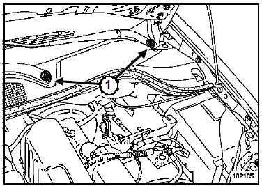
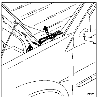
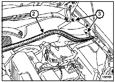
- Remove:
- the engine covers,
- the wiper arm nuts (1),
- the wiper arms,
- the left and right pillars,
- the bulkhead seal (2),
- the plastic rivets (3),
- the cowl grille,
- the water box partition.
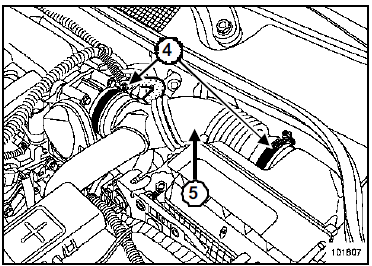
- Loosen the air duct clamps (4).
- Remove the air duct (5).
- Disconnect:
- the brake booster vacuum hose on the air distributor side,
- the ignition coil connectors,
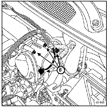
- the throttle body connector.
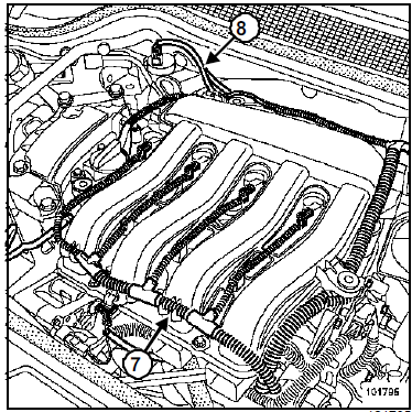
- Unclip the fuel vapour recirculation hose (8).
- Remove:
- the throttle body mounting bolts (6),
- the throttle body.
- Disconnect the air temperature sensor.
- Remove the engine harness (7).
- Remove:
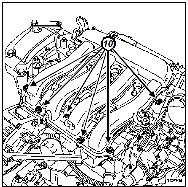
- the air distributor housing mounting bolts (10),
- the air distributor housing,
- the heat shield mountings.
- Remove the heat shield.
- Remove the lifting eye on the hydraulic unit side.
B84 or C84 or S84, and AIR CONDITIONING or AUTOMATIC AIR CONDITIONING
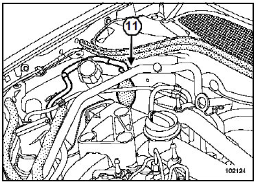
- Remove the air conditioning pipe (11) between the bulkhead flange and the receiver/drier.
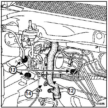
- Remove:
- the condensate drain channel (12),
- the ABS ECU earth terminal mounting bolt (14).
- Disconnect the ECU connector.
- Unscrew the six pipes from the hydraulic unit.
- Unclip the six pipes from the hydraulic unit.
- Remove:
- the hydraulic unit bracket mounting bolts (13),
- the "hydraulic unit bracket - hydraulic unit" assembly,
- the hydraulic unit.
INSTALLATION
- Refit in the reverse order of removal.
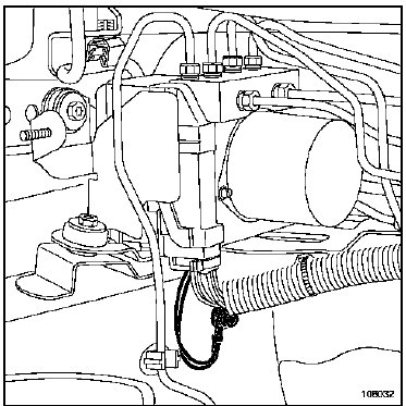
Position the earth terminal with the wires facing down to optimise the seal of the hydraulic unit ECU connector.
- Tighten to the following torques:
- the hydraulic unit to its bracket mounting bolts (0.8 daN.m),
- the pipe mounting bolts on the hydraulic unit (1.7 daN.m),
- the hydraulic unit bracket to body bolts (6.5 daN.m),
- the air distributor mounting bolts (0.9 daN.m).
B84 or C84 or S84, and AIR CONDITIONING or AUTOMATIC AIR CONDITIONING
- Tighten the air conditioning pipe mounting bolts to torque (0.8 daN.m).
- Always replace the throttle body seal when it is removed. When the ignition is switched on, the throttle body must carry out a learning cycle for the minimum and maximum stops. Use the diagnostic tool to check that this learning has been carried out correctly.
- Always replace the seals at the ends of the air conditioning pipe with new seals.
- Connect the battery; carry out the necessary relearn procedures (see Battery chapter).
- Bleed the brake circuit using the diagnostic tool (see General, Bleeding the brake circuit, page 30A-5).
B84 or C84 or S84, and AIR CONDITIONING or AUTOMATIC AIR CONDITIONING
- Refill the refrigerant circuit using the charging station tool.
- Check the air conditioning operates correctly with the fan unit at maximum speed.
- If there is no cooling, carry out a leak check (see Leak Detection).
- Torque the battery cover screws (0.4 daN.m).
F9Q or K9K
Essential equipment |
| charging station |
| pedal press |
| diagnostic tool |
Tightening torques |
|
| hydraulic unit to its bracket mounting bolts | 0.8 daN.m |
| pipe mounting bolts on the hydraulic unit | 1.7 daN.m |
| hydraulic unit bracket to body bolts | 6.5 daN.m |
| air conditioning pipe fixing screw | 0.8 daN.m |
| battery cover screw | 0.4 daN.m |

REMOVAL
- Position the vehicle on a two-post lift.
- Disconnect the battery, starting with the negative terminal.
AIR CONDITIONING or AUTOMATIC AIR CONDITIONING
- Drain the refrigerant circuit using the charging station tool.
- Remove:
- the right-hand wheel,
- the mudguards,
- the bumper,
- the air conditioning pipe clamp fixing screw on the bulkhead side,
- the air conditioning pipe clamp fixing screw on the receiver/drier side.
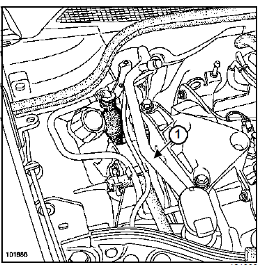
- Remove the air conditioning pipe (1) between the bulkhead clamp and the receiver/drier.
- Fit the brake pedal depressor tool on the brake pedal to limit brake fluid flow.
- Remove:
- the engine covers,
- the lifting ring,
- the heat shield mountings.
- Remove the sound insulation.
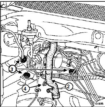
- Remove:
- the condensate drain channel (2),
- the earth terminal fixing screw (4) of the anti-lock braking system control unit.
- Disconnect the ECU connector.
- Unscrew the six pipes from the hydraulic unit.
- Unclip the six pipes from the hydraulic unit.
- Remove:
- the hydraulic unit bracket fixing screws (3),
- the "hydraulic unit bracket - hydraulic unit" assembly,
- the hydraulic unit to bracket mounting bolts,
- the hydraulic unit.
INSTALLATION
- Refit in the reverse order of removal.
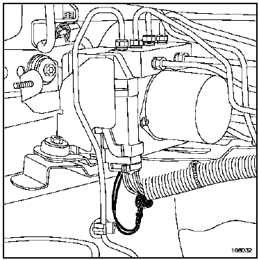
Position the earth terminal with the wires facing down to optimise the seal of the hydraulic unit ECU connector.
- Tighten to the following torques:
- the hydraulic unit to its bracket mounting bolts (0.8 daN.m),
- the pipe mounting bolts on the hydraulic unit (1.7 daN.m),
- the hydraulic unit bracket to body screws (6.5 daN.m).
AIR CONDITIONING or AUTOMATIC AIR CONDITIONING
- Tighten the air conditioning pipe fixing screws to torque (0.8 daN.m).
- Always replace the seals at the ends of the air conditioning pipe with new seals.
- Connect the battery; carry out the necessary relearn procedures (see Battery chapter).
- Bleed the hydraulic unit using the diagnostic tool (Chapter General, Bleeding the Brake Circuit, page 30A-5).
AIR CONDITIONING or AUTOMATIC AIR CONDITIONING
- Refill the refrigerant circuit using the charging station tool.
- Check the air conditioning operates correctly with the fan unit at maximum speed.
- If there is no cooling, carry out a leak check (see Leak Detection).
- Torque the battery cover screws (0.4 daN.m).
F4R
Essential equipment |
| charging station |
| pedal press |
| diagnostic tool |
Tightening torques |
|
| hydraulic unit mounting bolt on bracket | 0.8 daN.m |
| pipe mounting bolts on the hydraulic unit | 1.7 daN.m |
| hydraulic unit bracket to body bolts | 6.5 daN.m |
| air distributor mounting bolts | 0.9 daN.m |
| air conditioning pipe mounting bolt | 0.8 daN.m |
| BA cover bolts | 0.4 daN.m |

REMOVAL
- Disconnect the battery, starting with the negative terminal.
AIR CONDITIONING or AUTOMATIC AIR CONDITIONING
- Remove:
- the front right wheel,
- the mudguard,
- the undershield.
- Drain the refrigerant circuit using the charging station tool.
- Fit the brake pedal depressor tool on the brake pedal to limit brake fluid flow.
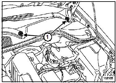
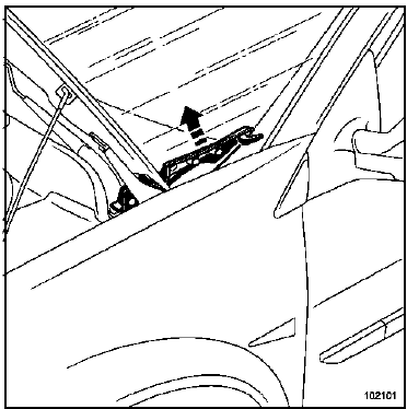
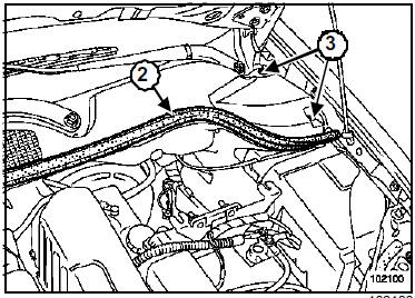
- Remove:
- the engine covers,
- the wiper arm nuts (1),
- the wiper arms,
- the left and right pillars,
- the bulkhead seal (2),
- the plastic rivets (3),
- the cowl grille,
- the water box partition.
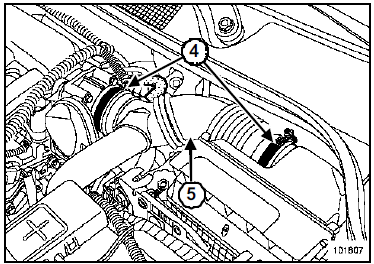
- Loosen the air duct clamps (4).
- Remove the air duct (5).
- Disconnect:
- the brake booster vacuum hose on the air distributor side,
- the ignition coil connectors,
- the throttle body connector.
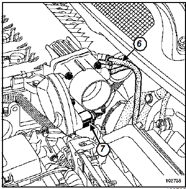
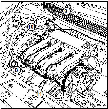
- Unclip the petrol vapour recirculation pipe on the solenoid valve (9) side.
- Disconnect:
- the air pressure sensor (10),
- the air temperature sensor (8).
- Remove the engine harness (11).
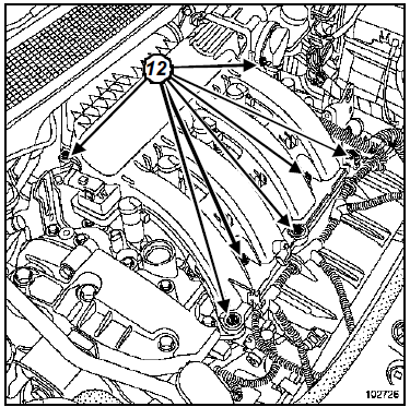
- Remove:
- the air distributor housing mounting bolts (12),
- the air distributor housing,
- the heat shield mountings.
- Remove the heat shield.
- Remove the lifting eye on the hydraulic unit side.
AIR CONDITIONING or AUTOMATIC AIR CONDITIONING
- Remove:
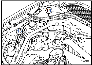
- the air conditioning pipe (14) between the bulkhead clamp and the receiver/drier,
- the windscreen washer reservoir channel (13).
- Remove:
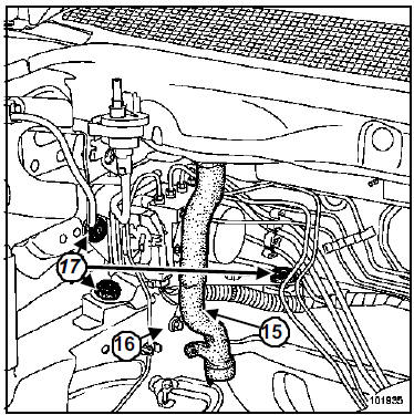
- the condensate drain channel (15),
- the earth terminal fixing screw (16) of the anti-lock braking system control unit.
- Disconnect the ECU connector.
- Unscrew the six pipes from the hydraulic unit.
- Unclip the six pipes from the hydraulic unit.
- Remove:
- the hydraulic unit bracket fixing screws (17),
- the "hydraulic unit bracket - hydraulic unit" assembly,
- the hydraulic unit bracket fixing screws.
- the hydraulic unit.
INSTALLATION
- Refit in the reverse order of removal.
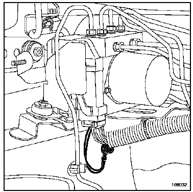
Position the earth terminal with the wires facing down to optimise the seal of the hydraulic unit ECU connector.
- Tighten to the following torques:
- the hydraulic unit to bracket mounting bolts (0.8 daN.m),
- the pipe mounting bolts on the hydraulic unit (1.7 daN.m),
- the hydraulic unit bracket to body bolts (6.5 daN.m),
- the air distributor mounting bolts (0.9 daN.m).
AIR CONDITIONING or AUTOMATIC AIR CONDITIONING
- Tighten the air conditioning pipe mounting bolts to torque (0.8 daN.m).
- Refill the refrigerant circuit using the charging station tool.
- Check the air conditioning operates correctly with the fan unit at maximum speed.
- If there is no cooling, carry out a leak check (see Leak Detection).
- Replace the throttle body gasket every time it is removed.
- When the ignition is switched on, the throttle body must carry out a learning cycle of the minimum and maximum stops. Using the diagnostic tool, check that this learning has been completed correctly.
- Always replace the seals at the ends of the air conditioning pipe with new seals.
- Connect the battery; carry out the necessary relearn procedures (see Battery chapter).
- Bleed the brake circuit using the diagnostic tool (see General, Bleeding the brake circuit, page 30A-5).
- Torque the battery cover screws (0.4 daN.m).
Test yourself
A quick Renault Megane quiz: every answer comes with an explanation and a link to the manual page.
Was this page helpful?