Command interpretation
KEYLESS VEHICLE - ACCESS
| AC004 | CENTRAL LOCKING OF OPENINGS |
INSTRUCTIONS
No fault must be present or stored.
This command tests the operation of the locking relays.
This command lasts 7 seconds.
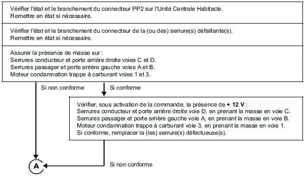
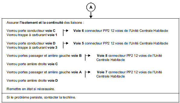
Note: The driver's door circuit is shared with the fuel filler flap circuit.
One or more doors do not lock when the command is activated.
AFTER REPAIR
Carry out a new system diagnosis.
Clear the stored faults.
Deal with any other faults.
| AC005 AC006 |
UNLOCKING OF OPENINGS DRIVER UNLOCKING |
INSTRUCTIONS
No fault must be present or stored.
This command tests the operation of the unlocking relays.
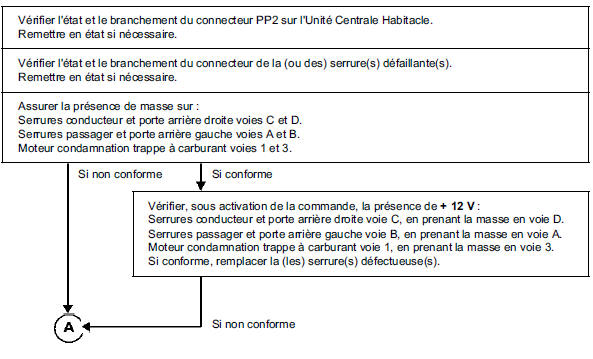
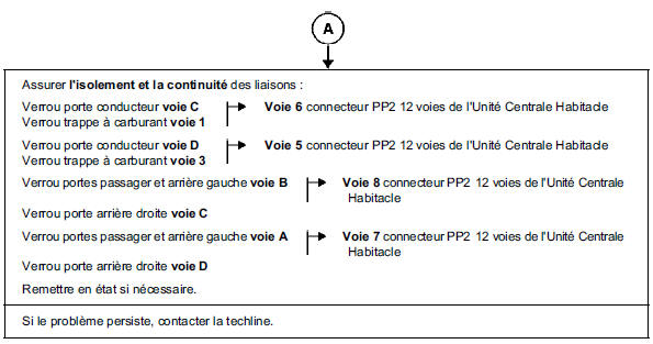
The driver's door circuit is shared with the fuel filler flap circuit.
This command lasts 7 seconds.
One or more doors do not unlock when the commands are activated.
AFTER REPAIR
Carry out a new system diagnosis.
Clear the stored faults.
Deal with any other faults.
| AC020 | CPE BUTTON INDICATOR |
INSTRUCTIONS
No fault must be present or stored.
This command checks whether the button is powered.
This command lasts 7 seconds.
| The CPE button light does not come on when the command is activated. |
| Check the condition and connection of the CPE button connector. Repair if necessary. |
| Check for a ground on pin 5 of the CPE button connector. Repair if necessary. |
| With the command activated, check for +12 V on pin 5 of the CPE button connector. If conforming, replace the switch. |
| Check the condition and connection of the PE2 connector on the Cabin Central Unit. Repair if necessary. |
| Check insulation and continuity of the circuit: Start switch pin 5 → Pin 14 of the 40-pin PE2 connector on the Cabin Central Unit Repair if necessary. |
| If the problem persists, contact Techline. |
AFTER REPAIR
Carry out a new system diagnosis.
Clear the stored faults.
Deal with any other faults.
| AC029 | CHILD SAFETY INDICATOR |
INSTRUCTIONS
No fault must be present or stored.
This command tests the operation of the child safety indicator.
This command lasts 7 seconds.
| The child safety switch light does not come on when the command is activated. |
| Check the condition and connection of the child safety switch connector. Repair if necessary. |
| Check for +12 V on pin A2 of the start switch connector. Repair if necessary. |
| With the command activated, check for a ground on pin B3 of the child safety switch connector. If conforming, replace the switch. |
| Check the condition and connection of the PE1 connector on the Cabin Central Unit. Repair if necessary. |
| Check insulation and continuity of the circuit: Start switch pin A2 → Pin 9 of the 40-pin PE1 connector on the Cabin Central Unit Repair if necessary. |
| If the problem persists, contact Techline. |
AFTER REPAIR
Carry out a new system diagnosis.
Clear the stored faults.
Deal with any other faults.
| AC025 | ONE-TOUCH WINDOW LIFT AUTHORIZATION |
INSTRUCTIONS
No fault must be present or stored.
This command activates the window regulator motors after replacing the Passenger Compartment Control Unit or after a minor loss of authorization.
This command lasts 7 seconds.
After activation, read status ET087 "One-touch window lift authorization" to check that the state has changed.In case of a fault, refer to the troubleshooting for this condition.
AFTER REPAIR
Carry out a new system diagnosis.
Clear the stored faults.
Carry out diagnosis of any other faults.
| AC032 | EXTERIOR ANTENNA TEST DRIVER SIDE |
INSTRUCTIONS
Before running this command, it is essential to check for antenna faults using command AC037 "Transmitting Antenna Diagnosis".
No fault must be present or stored.
During this command, isolate the vehicle from other Mégane II vehicles to ensure an accurate diagnosis.
Special feature
This command checks the operation of the driver-side exterior antennas.
If the range exceeds 1.50 m, check that the antennas are not short-circuited to ground.
This command lasts 1 minute.
Check that the badge reader flashes.
Front door
| Check the condition and connection of the 4-way black connector (bent or broken terminal tabs, etc.). Repair if necessary. |
| Check the condition and connection of the 40-way PE2 connector on the Passenger Compartment Central Unit (pins pushed back, broken, etc.). Repair if necessary. |
| Check insulation of the following links: 4-way connector pin 1 → Pin 27 of the 40-pin PE3 connector of the Passenger Compartment Control Unit Repair if necessary. |
| Replace the antenna if necessary. |
| If the problem persists, contact Techline. |
Rear door
| Check the condition and connection of the 4-way black connector (bent or broken terminal tabs, etc.). Repair if necessary. |
| Check the condition and connection of the 40-way PE2 connector on the Passenger Compartment Central Unit (pins pushed back, broken, etc.). Repair if necessary. |
| Check insulation of the following links: 4-way connector pin 1 → Pin 28 of the 40-pin PE3 connector of the Passenger Compartment Control Unit Repair if necessary. |
| Replace the antenna if necessary. |
| If the problem persists, contact Techline. |
AFTER REPAIR
Carry out a new system diagnosis.
Clear the stored faults.
Carry out diagnosis of any other faults.
| AC033 | EXTERIOR ANTENNA TEST PASSENGER SIDE |
INSTRUCTIONS
Before running this command, it is essential to check for antenna faults using command AC037 "Transmitting Antenna Diagnosis".
No fault must be present or stored.
During this command, isolate the vehicle from other Mégane II vehicles to ensure an accurate diagnosis.
Special feature
This command checks the operation of the passenger-side exterior antennas.
If the range exceeds 1.50 m, check that the antennas are not short-circuited to ground.
This command lasts 1 minute.
Check that the badge reader flashes.
Front door
| Check the condition and connection of the 4-way black connector (bent or broken terminal tabs, etc.). Repair if necessary. |
| Check the condition and connection of the 40-way PE2 connector on the Passenger Compartment Central Unit (pins pushed back, broken, etc.). Repair if necessary. |
| Check insulation to ground of the following links: 4-way connector pin 1 → Pin 31 of the 40-pin PE3 connector of the Passenger Compartment Control Unit Repair if necessary. |
| Replace the antenna if necessary. |
| If the problem persists, contact Techline. |
AFTER REPAIR
Carry out a new system diagnosis.
Clear the stored faults.
Deal with any other faults.
Rear door
| Check the condition and connection of the 4-way black connector (bent or broken terminal tabs, etc.). Repair if necessary. |
| Check the condition and connection of the 40-way PE2 connector on the Passenger Compartment Central Unit (pins pushed back, broken, etc.). Repair if necessary. |
| Check insulation to ground of the following links: 4-way connector pin 1 → Pin 32 of the 40-pin PE3 connector of the Passenger Compartment Control Unit Repair if necessary. |
| Replace the antenna if necessary. |
| If the problem persists, contact Techline. |
AFTER REPAIR
Carry out a new system diagnosis.
Clear the stored faults.
Carry out diagnosis of any other faults.
| AC033 | EXTERIOR ANTENNA TEST REAR CARGO AREA |
INSTRUCTIONS
Before running this command, it is essential to check for antenna faults using command AC037 "Transmitting Antenna Diagnosis".
No fault must be present or stored.
During this command, isolate the vehicle from other Mégane II vehicles to ensure an accurate diagnosis.
Special feature
This command checks the operation of the passenger-side exterior antennas.
If the range exceeds 1.50 m, check that the antennas are not short-circuited to ground.
This command lasts 1 minute.
Check that the badge reader flashes.
| Check the condition and connection of the 4-way black connector (bent or broken terminal tabs, etc.). Repair if necessary. |
| Check the condition and connection of the 40-way PE2 connector on the Passenger Compartment Central Unit (pins pushed back, broken, etc.). Repair if necessary. |
| Check insulation to ground of the following links: 4-way connector pin 1 → Pin 29 of the 40-pin PE3 connector of the Passenger Compartment Control Unit Repair if necessary. |
| Replace the antenna if necessary. |
| If the problem persists, contact Techline. |
AFTER REPAIR
Carry out a new system diagnosis.
Clear the stored faults.
Deal with any other faults.
| AC034 | INTERIOR ANTENNA TEST |
INSTRUCTIONS
Before running this command, it is essential to check for antenna faults using command AC037 "Transmitting Antenna Diagnosis".
No fault must be present or stored.
During this command, isolate the vehicle from other Mégane II vehicles to ensure an accurate diagnosis.
Special feature
This command checks the operation of the interior antennas.
If the range exceeds the door threshold, check that the antennas are not short-circuited to ground.
This command lasts 1 minute.
Check that the badge reader flashes.
| Check the condition and connection of the 3-way black connector (pins pushed back, broken, etc.). Repair if necessary. |
| Check the condition and connection of the 40-way PE2 connector on the Passenger Compartment Central Unit (pins pushed back, broken, etc.). Repair if necessary. |
| Checks insulation and continuity to ground of the following links: 3-way connector pin 1 → Pin 25 of the 40-pin PE3 connector of the Passenger Compartment Control Unit Repair if necessary. |
| Replace the antenna if necessary. |
| If the problem persists, contact Techline. |
AFTER REPAIR
Carry out a new system diagnosis.
Clear the stored faults.
Deal with any other faults.
| Check the condition and connection of the 3-way black connector (pins pushed back, broken, etc.). Repair if necessary. |
| Check the condition and connection of the 40-way PE2 connector on the Passenger Compartment Central Unit (pins pushed back, broken, etc.). Repair if necessary. |
| Check insulation to ground of the following links: 3-way connector pin 1 → Pin 35 of the 40-pin PE3 connector of the Passenger Compartment Control Unit Repair if necessary. |
| Replace the antenna if necessary. |
| If the problem persists, contact Techline. |
AFTER REPAIR
Carry out a new system diagnosis.
Clear the stored faults.
Deal with any other faults.
| Check the condition and connection of the 3-way black connector (pins pushed back, broken, etc.). Repair if necessary. |
| Check the condition and connection of the 40-way PE2 connector on the Passenger Compartment Central Unit (pins pushed back, broken, etc.). Repair if necessary. |
| Check insulation to ground of the following links: 3-way connector pin 1 → Pin 26 of the 40-pin PE3 connector of the Passenger Compartment Control Unit Repair if necessary. |
| Replace the antenna if necessary. |
| If the problem persists, contact Techline. |
AFTER REPAIR
Carry out a new system diagnosis.
Clear the stored faults.
Deal with any other faults.
| AC037 | TRANSMITTING ANTENNA DIAGNOSIS |
INSTRUCTIONS
No fault must be present or stored
Special feature
This command diagnoses the antennas for open circuit or short circuit to +12 V.
This command lasts 1 minute.
After activating the command, read the faults.If one or more antenna faults appear, refer to the troubleshooting for those faults.
AFTER REPAIR
Carry out a new system diagnosis.
Clear the stored faults.
Deal with any other faults.
| SC005 | BADGE CHECK |
This command indicates whether the badge is blank, the badge's assignment to the vehicle, the badge type and the badge frequency.Normal Operation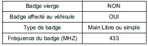 |
Abnormal Operation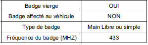 This badge is blank. You can perform the assignment procedure. |
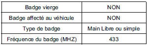 This badge does not belong to the vehicle; it belongs to another vehicle type. |
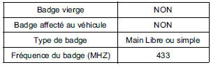 This badge does not belong to the vehicle; it belongs to the Mégane II vehicle type. |
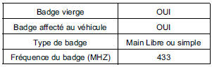 Contact your techline. |
KEYLESS VEHICLE - PROTECTION
| AC003 | IMMOBILIZER WARNING LIGHT |
INSTRUCTIONS
No fault must be present or stored.
The instrument panel must be detected on the multiplexed network.
This command tests the operation of the immobilizer warning light.
This command lasts 7 seconds.
| The immobilizer warning light does not come on when the command is activated. |
| Check the condition and connection of the instrument panel connector. Repair if necessary. |
| With the command activated, check for ground on pin 29 of the instrument panel. If OK, replace the instrument panel. |
| Check the condition and connection of the PE2 connector on the Cabin Central Unit. Repair if necessary. |
| Check insulation and continuity of the circuit: Instrument panel pin 29 → Pin 29 of the 40-pin PE2 connector of the Passenger Compartment Control Unit Repair if necessary. |
| If the fault persists, contact Techline. |
AFTER REPAIR
Carry out a new system diagnosis.
Clear the stored faults.
Deal with any other faults.
| AC026 | START SWITCH LIGHTING |
INSTRUCTIONS
No fault must be present or stored.
This command tests the operation of the start switch lighting. This command lasts 7 seconds.
| The start switch lighting does not come on when the command is activated. |
| Check the condition and connection of the start switch connector. Repair if necessary. |
| Check for ground on pin 2 of the start switch connector. Repair if necessary. |
| With the command activated, check for +12 V on pin 4 of the start switch connector. If conforming, replace the switch. |
| Check the condition and connection of the PE1 connector on the Cabin Central Unit. Repair if necessary. |
| Check insulation and continuity of the circuit: Start switch pin 4 → Pin 13 of the 40-pin PE1 connector of the Passenger Compartment Control Unit Repair if necessary. |
| If the problem persists, contact Techline. |
AFTER REPAIR
Carry out a new system diagnosis.
Clear the stored faults.
Deal with any other faults.
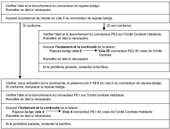
| AC024 | BADGE HOLDER LIGHTING |
INSTRUCTIONS
No fault must be present or stored.
This command tests the operation of the badge holder.
This command lasts 7 seconds.
The badge holder lighting does not come on when the command is activated.
AFTER REPAIR
Carry out a new system diagnosis.
Clear the stored faults.
Deal with any other faults.
AIR CONDITIONING - HEATING
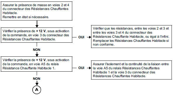
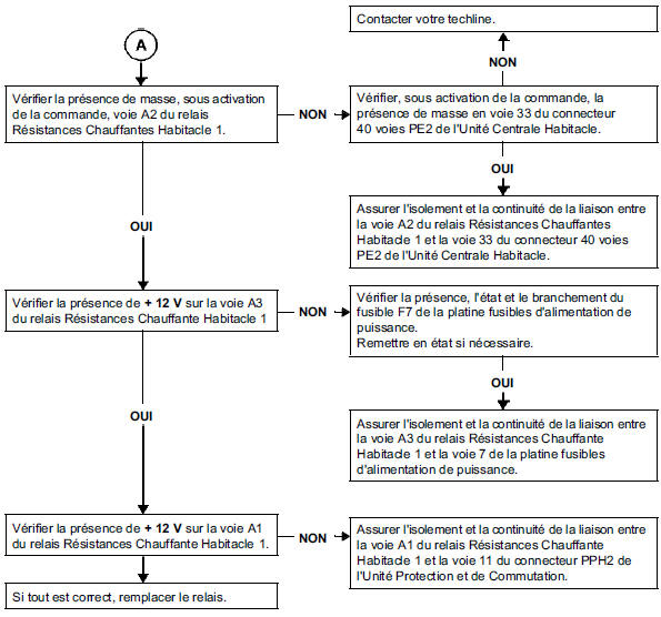
| AC016 | RCH RELAY 1 |
INSTRUCTIONS
Check that the vehicle is equipped with cabin heating resistors.
No fault must be present or stored.
This command tests the operation of the cabin heating resistors.
This command lasts 7 seconds.
AFTER REPAIR
Carry out a new system diagnosis.
Clear the stored faults.
Deal with any other faults.
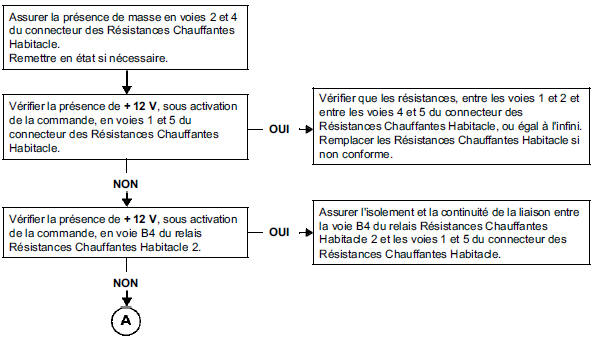
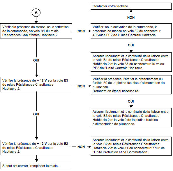
| AC017 | RCH RELAY 2 |
INSTRUCTIONS
Check that the vehicle is equipped with cabin heating resistors.
No fault must be present or stored.
This command tests the operation of the cabin heating resistors.
This command lasts 7 seconds.
AFTER REPAIR
Carry out a new system diagnosis.
Clear the stored faults.
Deal with any other faults.
AIR CONDITIONING - USER SELECTION
| AC015 | A/C BUTTON INDICATOR LIGHT Manual air conditioning only |
INSTRUCTIONS
No fault must be present or stored.
This command tests the operation of the air conditioning indicator light.
Switch the ignition on; the air conditioning control panel must light up.
This command lasts 7 seconds.
| The indicator light does not come on when the command is activated. |
| Check the condition and connection of the heating control panel connector. Repair if necessary. |
| Check for ground on pin 5 of the heating control panel connector. Repair if necessary. |
| With the command activated, check for +12 V on pin 6 of the heating control panel connector. If not OK, replace the control panel. |
| If not OK, replace the control panel. Check the condition and connection of the PE2 connector on the Cabin Central Unit. Repair if necessary. |
| Check insulation and continuity of the circuit: Control panel pin 6 → Pin 26 of the 40-pin PE2 connector on the Passenger Compartment Central Unit Repair if necessary |
| If the problem persists, contact Techline. |
AFTER REPAIR
Carry out a new system diagnosis.
Clear the stored faults.
Deal with any other faults.
| AC019 | REAR WINDOW HEATING INDICATOR Except with automatic climate control. |
INSTRUCTIONS
No fault must be present or stored.
This command tests the operation of the rear window heating indicator.
Switch ignition on.
This command lasts 7 seconds.
| The rear window heating indicator does not light when the command is activated. |
| Check the condition and connection of the heating control panel connector. Repair if necessary. |
| Check for ground on pin 5 of the heating control panel connector. Repair if necessary. |
| With the command activated, check for +12 V on pin 4 of the heating control panel connector. If not OK, replace the control panel. |
| Check the condition and connection of the PE2 connector on the Cabin Central Unit. Repair if necessary. |
| Check insulation and continuity of the circuit: Control panel pin 4 → Pin 38 of the 40-pin PE2 connector on the Passenger Compartment Central Unit Repair if necessary. |
| If the problem persists, contact Techline. |
AFTER REPAIR
Carry out a new system diagnosis.
Clear the stored faults.
Deal with any other faults.
LIGHTING - LIGHTING POWER
| AC009 | REAR FOG LIGHTS |
INSTRUCTIONS
No fault must be present or stored.
This command tests the operation of the rear fog light.
Check the bulbs.
The rear fog lamps do not come on when the command is activated.Left-hand turn
| Check the condition and connection of the connector on each rear light. Repair if necessary. |
| Check for ground: Saloon 3-door and 5-door: on pin 1 of the black rear light connector. 4-door saloon: on pin 2 of the rear light connector. Estate: on pin 3 of the rear light connector. Convertible: on pin 3 of the rear light connector. Repair if necessary. |
| With the command activated, check for +12 V: Saloon 3-door and 5-door: on pin 2 of the black rear light connector. Saloon 4-door: on pin 6 of the rear light connector. Estate: on pin 1 of the rear light connector. Convertible: on pin 1 of the rear light connector. If OK, check the bulbs again. If still not OK, replace the rear light. |
| Check the condition and connection of the PP3 connector on the Cabin Central Unit. Repair if necessary. |
Check insulation and continuity of the wiring: |
| If the problem persists, contact Techline. |
AFTER REPAIR
Carry out a new system diagnosis.
Clear the stored faults.
Deal with any other faults.
Right-hand turn
| Check the condition and connection of the connector on each rear light. Repair if necessary. |
| Check for ground: Saloon 3-door and 5-door: on pin 4 of the black rear light connector. 4-door saloon: on pin 5 of the rear light connector. Estate: on pin 3 of the rear light connector. Convertible: on pin 4 of the rear light connector. Repair if necessary. |
| With the command activated, check for +12 V: Saloon 3-door and 5-door: on pin 3 of the black rear light connector. 4-door saloon: on pin 1 of the rear light connector. Estate: on pin 1 of the rear light connector. Convertible: on pin 6 of the rear light connector. If OK, check the bulbs again. If still not OK, replace the rear light. |
| Check the condition and connection of the PP3 connector on the Cabin Central Unit. Repair if necessary. |
Check insulation and continuity of the wiring: |
| If the problem persists, contact Techline. |
AFTER REPAIR
Carry out a new system diagnosis.
Clear the stored faults.
Deal with any other faults.
| AC022 | LEFT-HAND TURN SIGNAL |
INSTRUCTIONS
No fault must be present or stored.
This command tests the operation of the turn signals.
Switch ignition on.
Check the bulbs.
| The turn signals do not light when the command is activated. |
| Check the condition and connection of the connectors on the left headlight, left side repeater and left rear light. Repair if necessary. |
| Check for ground on the faulty component: Pin 1 headlight without Xenon bulb / Pins 1 and 4 headlight with Xenon bulb. Pin 2 side repeater. Rear light: Saloon 3-door and 5-door: on pin 3 of the black rear light connector. 4-door saloon: on pin 2 of the rear light connector. Estate: on pin 3 of the rear light connector. Convertible: on pin 3 of the rear light connector. Repair if necessary. |
| With the command activated, check for +12 V on the faulty component: Pin 3 headlight without Xenon bulb / Pin 8 headlight with Xenon bulb Rear light: Saloon 3-door and 5-door: on pin 2 of the black rear light connector. 4-door saloon: on pin 1 of the rear light connector. Estate: on pin 2 of the rear light connector. Convertible: on pin 2 of the rear light connector. If OK, check the bulbs again. If still not OK, replace the rear light(s). |
| Check the condition and connection of the PP3 connector on the Cabin Central Unit. Repair if necessary. |
Check insulation and continuity of the wiring: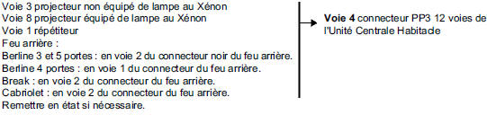 |
| If the problem persists, contact Techline. |
AFTER REPAIR
Carry out a new system diagnosis.
Clear the stored faults.
Deal with any other faults.
| AC023 | RIGHT-HAND TURN SIGNAL |
INSTRUCTIONS
No fault must be present or stored.
This command tests the operation of the turn signals.
Switch ignition on.
Check the bulbs.
| The turn signals do not light when the command is activated. |
| Check the condition and connection of the connectors of the right headlight, right side repeater and right rear light. Repair if necessary. |
| Check for ground on the faulty component: Pin 1 headlight without Xenon bulb / Pins 1 and 4 headlight with Xenon bulb Rear light: Saloon 3-door and 5-door: on pin 3 of the black rear light connector. 4-door saloon: on pin 5 of the rear light connector. Estate: on pin 3 of the rear light connector. Convertible: on pin 4 of the rear light connector. Repair if necessary. |
| With the command activated, check for +12 V on the faulty component: Pin 3 headlight without Xenon bulb / Pin 8 headlight with Xenon bulb Rear light: Saloon 3-door and 5-door: on pin 2 of the black rear light connector. Saloon 4-door: on pin 6 of the rear light connector. Estate: on pin 2 of the rear light connector. Convertible: on pin 5 of the rear light connector. Repair if necessary. If OK, check the bulbs again. If still not OK, replace the rear light(s). |
| Check the condition and connection of the PP3 connector on the Cabin Central Unit. Repair if necessary. |
| If the problem persists, contact Techline. |
| Check the condition and connection of the PP3 connector on the Cabin Central Unit. Repair if necessary. |
Check insulation and continuity of the wiring: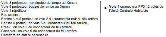 |
| If the problem persists, contact Techline. |
AFTER REPAIR
Carry out a new system diagnosis.
Clear the stored faults.
Deal with any other faults.
| AC021 | INTERIOR LIGHT CONTROL |
INSTRUCTIONS
No fault must be present or stored.
This command tests the operation of the interior light.
Check the bulbs.
| The interior lights do not light when the command is activated. |
| Check the condition and connection of the interior light connectors. Repair if necessary. |
| Check for ground on pin 3 of each interior light. Repair if necessary. |
| With the command activated, check for +12 V on pin 2 of each interior light. If OK, check the bulbs again. If still not OK, replace the interior light(s). |
| Check the condition and connection of the PP3 connector on the Cabin Central Unit. Repair if necessary. |
| Check insulation and continuity of the circuit: Pin 2 of each interior light → Pin 1 of the 12-pin PP3 connector on the Passenger Compartment Central Unit Repair if necessary. |
| If the problem persists, contact Techline. |
AFTER REPAIR
Carry out a new system diagnosis.
Clear the stored faults.
Deal with any other faults.
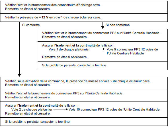
| AC027 | FOOTWELL LIGHTING |
INSTRUCTIONS
No fault must be present or stored.
This command tests the operation of the footwell lighting.
Check the bulbs.
AFTER REPAIR
Carry out a new system diagnosis.
Clear the stored faults.
Deal with any other faults.
WIPING - WIPER POWER
| AC007 | REAR WIPER |
INSTRUCTIONS
No fault must be present or stored.
This command tests the operation of the rear wiper.
This command lasts 7 seconds.
| The rear wiper does not operate when the command is activated. |
| Check the condition and connection of the rear wiper motor connector. Repair if necessary. |
| Check ground on pin 3 of the rear wiper connector. Repair if necessary. |
| With the command activated, check for +12 V on pin 1 of the rear wiper connector. If everything is OK, replace the rear wiper motor. |
| Check the condition and connection of the PE3 connector on the Passenger Compartment Central Unit. Repair if necessary. |
| Check insulation and continuity of the circuit: Motor pin 1 → Pin 37 of the 40-pin PE3 connector on the Passenger Compartment Central Unit. Repair if necessary. |
| If the problem persists, contact Techline. |
AFTER REPAIR
Carry out a new system diagnosis.
Clear the stored faults.
Deal with any other faults.
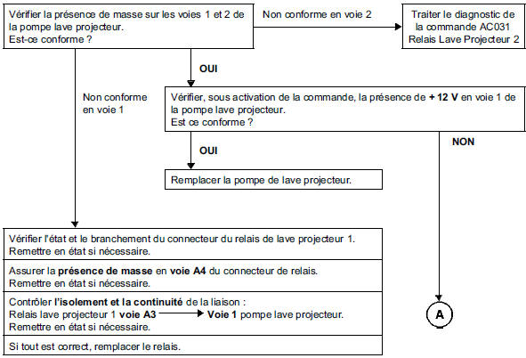
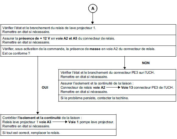
| AC030 | HEADLAMP WASHER RELAY 1 |
INSTRUCTIONS
No fault must be present or stored.
This command tests the operation of headlamp washer 1.
This command lasts 7 seconds.
AFTER REPAIR
Carry out a new system diagnosis.
Clear the stored faults.
Deal with any other faults.
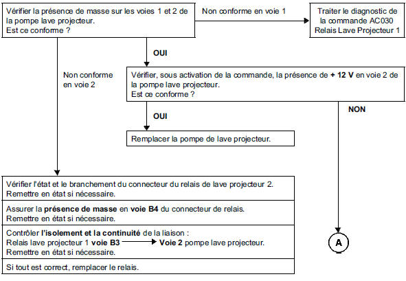
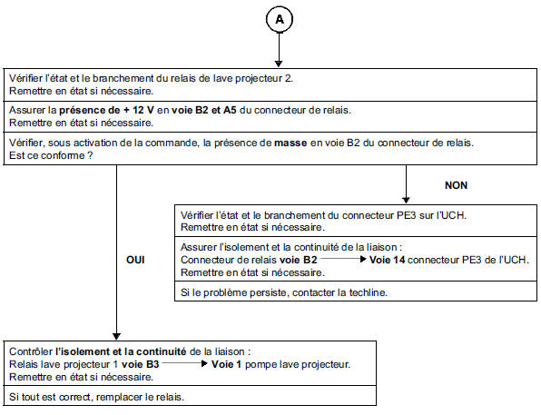
| AC031 | HEADLAMP WASHER RELAY 2 |
INSTRUCTIONS
No fault must be present or stored.
This command tests the operation of headlamp washer 2.
This command lasts 7 seconds.
AFTER REPAIR
Carry out a new system diagnosis.
Clear the stored faults.
Deal with any other faults.
Test yourself
A quick Renault Megane quiz: every answer comes with an explanation and a link to the manual page.