Interpreting states
KEYLESS VEHICLE - ACCESS
| ET041 | OPENING REAR WINDOW |
INSTRUCTIONS
No fault must be present or stored.
This status is only usable for vehicles of type J (Scénic, 5 seats), R (Scénic 7 seats) and K (Estate).
| Check the condition and connection of the 40-way PE3 connector on the Cabin Central Unit (bent, broken or corroded tabs, etc.). Repair if necessary. |
| Check the condition and connection of the grey 8-way connector of the opening rear window switch (bent, broken or corroded tabs, etc.). Repair if necessary. |
| Check insulation and continuity of the link: Lock connector 4-way pin 3 → pin 14 of 40-way connector PE3 on the Cabin Central Unit. Repair if necessary. |
| Check: insulation of the lock switch between pins 3 and 4 in rest position. Continuity of the lock switch between pins 3 and 4 in engaged position. Replace the lock if not compliant. |
| If problem persists, contact Techline. |
AFTER REPAIR
Carry out a new system diagnosis.
Clear the stored faults.
Deal with any other faults.
| ET042 | PASSENGER DOOR |
INSTRUCTIONS
Check that no fault is present.
| Check the condition and connection of the 40-way PE1 connector on the Cabin Central Unit (bent, broken or corroded tabs, etc.). Repair if necessary. |
| Check the condition and connection of the black 4-way passenger door lock connector (bent, broken or corroded tabs, etc.). Repair if necessary. |
| Check continuity and insulation of the link: Passenger lock black 4-way pin A Repair if necessary. |
| Check: insulation of the lock switch between pins B and A in rest position. Continuity of the lock switch between pins B and A in engaged position. Replace the lock if not compliant. |
| If the problem persists, contact Techline. |
AFTER REPAIR
Carry out a new system diagnosis.
Clear the stored faults.
Deal with any other faults.
| ET043 | CAR FUNCTION AUTHORISATION BY CPE |
INSTRUCTIONS
No fault must be present or stored.
Check that the Cabin Central Unit is configured with Locking while driving. With ignition in accessory position, press and hold the vehicle locking button for more than 5 seconds to activate automatic locking (the locking-while-driving state is active).Press and hold the vehicle unlock button for more than 5 seconds with the ignition on to disable automatic locking while driving (the auto-lock while driving state becomes inactive).
Press and hold the vehicle lock button for more than 5 seconds with the ignition off to lock the vehicle (Spain specification).
AFTER REPAIR
Carry out a new system diagnosis.
Clear the stored faults.
Deal with any other faults.
| ET044 | CPE BUTTON |
INSTRUCTIONS
No fault must be present or stored.
| Check the condition and connection of the 40-way PE1 connector on the Cabin Central Unit (bent, broken or corroded tabs, etc.). Repair if necessary. |
| Check the condition and connection of the grey 8-pin connector of the electric door locking switch (pushed-back, broken or corroded tabs, etc.). Repair if necessary. |
| Check continuity and insulation of the link: Electric door locking switch 8-pin, pin 5 → pin 14 of the 40-pin PE1 connector on the Body Control Unit. Repair if necessary. |
| Check the continuity of pin 4 of the 8-pin connector and vehicle ground. Repair if necessary. |
| Check: Switch continuity between pins 5 and 2 (switch pressed). Switch insulation between pins 5 and 2 (switch at rest). Replace the switch if not compliant. |
| If the fault persists, contact Techline. |
AFTER REPAIR
Carry out a new system diagnosis.
Clear the stored faults.
Deal with any other faults.
| ET045 | RF FRAME RECEIVED |
INSTRUCTIONS
No fault must be present or stored.
Note: This state is used for the TPMS function, unlocking-locking and keyless start.
This state only checks the condition of the Body Control Unit receiving antenna.
| ET045 "NO" when one of the fob buttons is pressed, or with sensor detection faults on the Tyre Pressure Monitoring System function. |
| Check with the second vehicle key fob. If the state changes to "YES", check ET066 "Fob button press received". |
| If the state remains "NO", test with another fob from a different MEGANE II vehicle. If the fault persists, contact your techline. |
AFTER REPAIR
Carry out a new system diagnosis.
Clear the stored faults.
Deal with any other faults.
| ET050 | TAILGATE |
INSTRUCTIONS
No fault must be present or stored.
| Check the condition and connection of the 40-way PE1 connector on the Cabin Central Unit (bent, broken or corroded tabs, etc.). Repair if necessary. |
| Check the condition and connection of the white 4-pin tailgate lock connector (pushed-back, broken or corroded tabs, etc.). Repair if necessary. |
| Check insulation and continuity of the link: White 4-pin tailgate lock, pin 3 → pin 8 of the 40-pin PE1 connector on the Body Control Unit. Repair if necessary. |
| Check: Tailgate lock contact insulation between pins 3 and 4 at rest. Tailgate lock contact continuity between pins 3 and 4 when engaged. Replace the lock if not compliant. |
| If the problem persists, contact Techline. |
AFTER REPAIR
Carry out a new system diagnosis.
Clear the stored faults.
Deal with any other faults.
| ET051 | REAR LEFT DOOR |
INSTRUCTIONS
No fault must be present or stored
| Check the condition and connection of the 40-way PE1 connector on the Cabin Central Unit (bent, broken or corroded tabs, etc.). Repair if necessary. |
| Check the condition and connection of the black 4-pin rear left door lock connector (pushed-back, broken or corroded tabs, etc.). Repair if necessary. |
| Check insulation and continuity of the link: Rear left lock black 4-pin, pin D → pin 19 of the 40-pin PE1 connector on the Body Control Unit. Repair if necessary. |
| Check: Lock contact insulation between pins C and D (door closed). Lock contact continuity between pins C and D (door closed). Replace the lock if not compliant. |
| If the problem persists, contact Techline. |
AFTER REPAIR
Carry out a new system diagnosis.
Clear the stored faults.
Deal with any other faults.
| ET052 | REAR RIGHT DOOR |
INSTRUCTIONS
No fault must be present or stored.
| Check the condition and connection of the 40-way PE1 connector on the Cabin Central Unit (bent, broken or corroded tabs, etc.). Repair if necessary. |
| Check the condition and connection of the black 4-pin rear left door lock connector (pushed-back, broken or corroded tabs, etc.). Repair if necessary. |
| Check continuity and insulation of the link: Rear right lock black 4-pin, pin A → pin 16 of the blue 40-pin connector on the Body Control Unit. Repair if necessary. |
| Check: Lock contact insulation between pins A and B (door closed). Lock contact continuity between pins A and B (door closed). Replace the lock if not compliant. |
| If the problem persists, contact Techline. |
AFTER REPAIR
Carry out a new system diagnosis.
Clear the stored faults.
Deal with any other faults.
| ET053 | DRIVER'S DOOR |
INSTRUCTIONS
No fault must be present or stored.
| Check the condition and connection of the 40-way PE1 connector on the Cabin Central Unit (bent, broken or corroded tabs, etc.). Repair if necessary. |
| Check the condition and connection of the black 4-pin rear left door lock connector (pushed-back, broken or corroded tabs, etc.). Repair if necessary. |
| Check insulation and continuity of the link: Driver's door lock black 4-pin, pin D → pin 17 of the 40-pin PE1 connector on the Body Control Unit. Repair if necessary. |
| Check: Lock contact insulation between pins C and D (door closed). Lock contact continuity between pins C and D (door closed). Replace the lock if not compliant. |
| If the problem persists, contact Techline. |
AFTER REPAIR
Carry out a new system diagnosis.
Clear the stored faults.
Deal with any other faults.
| ET054 | OPTICAL SENSOR POWERED (Vehicles equipped with keyless entry only) |
INSTRUCTIONS
After 72 hours without any attempt to open the vehicle, the Body Control Unit cuts power to the optical sensors.
To restore power to the optical sensors, pull the handle of one of the doors or unlock with the fob, then lock the vehicle and place your hand in one of the handles.
ET054: stays at "NO" despite an action on the door handles.
| The vehicle has been immobilised for less than 72 hours: Check that the Body Control Unit is configured for keyless entry using configuration reading LC001 "Keyless function". If everything is correct, contact Techline. |
| The vehicle has been immobilised for more than 72 hours: Check insulation from 12 V on the following pin (door handle pulled): pin 23 of the 40-pin PE3 connector on the Body Control Unit. Check ground on pin 23 of the 40-pin PE connector on the Body Control Unit while pulling a handle. Is it present? |
| YES | Contact your techline. |
| NO | Check continuity between pin 23 of the 40-pin PE3 connector and pin 2 of the black 3-pin optical sensor connector. Repair if necessary. Check ground on pin 3 of the connector; restore if necessary. Check the continuity of the handle-pulled contact between pins 1 and 2; if insulation is present, replace the handle. |
| If the fault persists, contact your techline. |
AFTER REPAIR
Carry out a new system diagnosis.
Clear the stored faults.
Deal with any other faults.
| ET055 ET056 ET057 |
DRIVER OPTICAL SENSOR REAR DRIVER OPTICAL SENSOR FRONT-REAR PASSENGER OPTICAL SENSOR (Vehicles equipped with keyless entry only) |
INSTRUCTIONS
No fault must be present or stored.
Switch the ignition on, then off.
Check that status ET054 "Optical sensor powered" is set to "YES".Place your hand behind the door handle; check that the corresponding state is "active". If the state is "inactive", lock the vehicle and pull the handle.
Is the state active?
| YES | Check the condition of the reflective surface inside the handle (frost, dirt). |
Check the condition of the optical sensor.
If necessary, replace the sensor.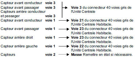
AFTER REPAIR
Carry out a new system diagnosis.
Clear the stored faults.
Carry out diagnosis of any other faults.
| ET058 ET059 |
DRIVER HANDLE LOCK BUTTON PASSENGER HANDLE LOCK BUTTON (Vehicles equipped with keyless entry only) |
INSTRUCTIONS
Check that no fault is present.
| Check the condition and connection of the blue 9-pin door connector (pushed-back, broken or corroded tabs, etc.). Repair if necessary. |
| Check the condition and connection of the 40-way PE3 connector on the Cabin Central Unit (bent, broken or corroded tabs, etc.). Repair if necessary. |
| Ensure ground is present on pin 4 of the door handle. Repair if necessary. |
| Check continuity and insulation of the link: Handle switch on pin 3 → pin 30 of the 40-pin PE3 connector on the Body Control Unit. Repair if necessary. |
| Check: Handle insulation between pins 3 and 4 (at rest position). Handle continuity between pins 3 and 4 (pressed position). Replace the handle if necessary. |
| If the fault persists, contact your techline. |
AFTER REPAIR
Carry out a new system diagnosis.
Clear the stored faults.
Carry out diagnosis of any other faults.
| ET060 | TAILGATE TRUNK LOCK BUTTON (Vehicles equipped with keyless entry only) |
INSTRUCTIONS
Check that no fault is present.
| Check the condition and connection of the white 2-pin tailgate lock button connector (pushed-back, broken or corroded tabs, etc.). Repair if necessary. |
| Check the condition and connection of the 40-way PE3 connector on the Cabin Central Unit (bent, broken or corroded tabs, etc.). Repair if necessary. |
| Ensure ground is present on pin 2 of the tailgate lock button. Repair if necessary. |
| Check continuity and insulation of the link: Tailgate lock button on pin 1 → pin 4 of the 40-pin PE3 connector on the Body Control Unit. Repair if necessary. |
| Check: Insulation between pins 1 and 2 of the tailgate button (at rest position). Continuity between pins 1 and 2 of the tailgate button (pressed position). Replace the button if necessary. |
| If the fault persists, contact your techline. |
AFTER REPAIR
Carry out a new system diagnosis.
Clear the stored faults.
Address any other faults present.
| ET061 | TAILGATE OPENING REQUEST |
INSTRUCTIONS
No fault must be present or stored.
ET061 "Absent" although there is a request from the button
Vehicle fitted with scenario 2 (hands-free): Check the condition and connection of the 40-way PE3 connector on the Cabin Central Unit.Repair if necessary.
Check for ground on pin 5 of the 40-pin PE3 connector, button pressed.
Is it present?
| YES | Contact your techline. |
| NO | Check the condition and connection of the 2-pin switch connector. Repair if necessary. Check for ground on pin 2 of the 2-pin switch connector. Check the continuity of the switch between pins 1 and 2 (button pressed). If there is an open circuit, replace the switch. Check the continuity between pin 5 of the 40-pin PE3 connector of the Body Control Unit and pin 1 of the 2-pin switch connector. Repair if necessary. |
AFTER REPAIR
Carry out a new system diagnosis.
Clear the stored faults.
Deal with any other faults.
ET061 "Absent" although there is a request from the button
Vehicle fitted with scenario 1 (non hands-free): Check the condition and connection of the 40-way PE3 connector on the Cabin Central Unit.Repair if necessary.
Check for ground on pin 1 of the 4-pin tailgate lock connector, button pressed.
Is it present?
| YES | Check for +12 V on pin 2 of the 4-pin lock connector. Is it present? YES: Replace the tailgate lock NO: Check +12 V on pin 7 of the PP3 connector of the Body Control Unit If +12 V is present, check the continuity and insulation of the following link: PP3 connector of the Body Control Unit pin 7 → pin 2 of the 4-pin lock connector Repair if necessary. If +12 V is not present, contact your techline. |
| NO | Check the continuity between pin 1 of the 2-pin switch connector and body ground. Repair if necessary. Check the continuity of the switch between pins 1 and 2. If there is an open circuit, replace the switch. |
AFTER REPAIR
Carry out a new system diagnosis.
Clear the stored faults.
Deal with any other faults.
ET061 "Present" although there is no request from the button
Vehicle equipped with scenario 2 (hands-free)
| Check the insulation from ground on pin 5 of the 40-pin PE3 connector of the Body Control Unit. Repair if necessary. |
| Check the insulation of the switch between pins 1 and 2. If there is continuity, replace the switch. |
| If the fault persists, contact your techline. |
Vehicle equipped with scenario 1 (non hands-free)
| Check the insulation from ground on pin 1 of the 4-pin lock connector. Repair if necessary. |
| Ensure the switch is insulated between pins 1 and 2. If there is continuity, replace the switch. |
| If the fault persists, contact your techline. |
AFTER REPAIR
Carry out a new system diagnosis.
Clear the stored faults.
Deal with any other faults.
| ET062 | REAR WINDOW OPENING REQUEST |
INSTRUCTIONS
No fault must be present or stored.
This status is only usable for vehicles of type J (Scénic, 5 seats), R (Scénic 7 seats) and K (Estate).
ET062 "Absent" although there is a request from the button.
Vehicle fitted with scenario 2 (hands-free): Check the condition and connection of the 40-way PE3 connector on the Cabin Central Unit.Repair if necessary.
Check for ground on pin 16 of the 40-pin PE3 connector, button pressed.
Is it present?
| YES | Contact your techline. |
| NO | Check the condition and connection of the 2-pin switch connector. Repair if necessary. Check the continuity between pin 16 of the 40-pin PE3 connector of the Body Control Unit and pin 1 of the 2-pin switch connector. Repair if necessary. Check for ground on pin 2 of the 2-pin switch connector. Check the continuity of the switch between pins 1 and 2. If there is an open circuit, replace the switch. |
AFTER REPAIR
Carry out a new system diagnosis.
Clear the stored faults.
Deal with any other faults.
ET062 "Absent" although there is a request from the button
Vehicle fitted with scenario 1 (non hands-free): Check the condition and connection of the 4-way lock connector.Repair if necessary.
Check for ground on pin 1 of the tailgate lock connector, button pressed.
Is it present?
| YES | Check for +12 V on pin 2 of the 4-pin lock connector. Is it present? YES: Replace the tailgate lock If +12 V is not present, contact your techline. |
| NO | Check the continuity between pin 1 of the 2-pin switch connector and body ground. Repair if necessary. Check the continuity of the switch between pins 1 and 2. If there is an open circuit, replace the switch. |
AFTER REPAIR
Carry out a new system diagnosis.
Clear the stored faults.
Carry out diagnosis of any other faults.
ET062 "Present" although there is no request from the button
Vehicle equipped with scenario 2 (hands-free)
| Check the insulation from ground on pin 7 of the Body Control Unit. Repair if necessary. |
| Check the insulation of the switch between pins 1 and 2. If there is continuity, replace the switch. |
| If the fault persists, contact your techline. |
Vehicle equipped with scenario 1 (hands-free)
| Check the insulation from ground on pin 4 of the lock. Repair if necessary. |
| Check the insulation of the switch between pins 1 and 2. If there is continuity, replace the switch. |
| If the fault persists, contact your techline. |
AFTER REPAIR
Carry out a new system diagnosis.
Clear the stored faults.
Deal with any other faults.
| ET066 | BADGE BUTTON PRESS RECEIVED |
INSTRUCTIONS
No fault must be present or stored.
The second badge must be present.
The status is shown as "YES" when one of the buttons is pressed.
ET066: "NO" despite pressing one of the buttons on the badge.
Check with the second badge whether the status changes to "YES".Replace the first badge.
If the status remains "NO", contact the techline.
AFTER REPAIR
Carry out a new system diagnosis.
Clear the stored faults.
Deal with any other faults.
| ET067 | BADGE BUTTON PRESS RECOGNISED |
INSTRUCTIONS
No fault must be present or stored.
The status is shown as "YES" when one of the buttons is pressed.
ET067: "NO" despite pressing one of the buttons on the badge
| Resynchronise the badges by forcing APC. |
| If the problem persists and ET066 "Badge button press received" is "YES", replace the badges. |
| If the fault persists, contact your techline. |
AFTER REPAIR
Carry out a new system diagnosis.
Clear the stored faults.
Deal with any other faults.
| ET068 ET069 |
LAST LOCKING SOURCE LAST UNLOCKING SOURCE |
INSTRUCTIONS
No fault must be present or stored.
Indicates which mode caused the last locking or unlocking.ET068 "Last locking source" C.A.R FUNCTION: the Body Control Unit controls locking based on the vehicle speed information.
AUTOMATIC: the Body Control Unit triggers locking if no door opening is detected, or if a hands-free or badge unlocking request is not received, within 30 s following an unlocking. Electric door locking: follows an action on the button.
HANDS-FREE: detection of a locking request by pressing the button on the handles or in the logic sequence.
BADGE: detection by a button press.
DIAGNOSTIC: action requested by the APV tool via command AC004 "Lock doors". ET069 "Last unlocking source" HANDS-FREE: detection of a hand in the handle; Electric door locking: follows an action on the button.
AIRBAG: following a detected impact signal.
DIAGNOSTIC: action requested by the APV tool via command AC005 "Unlock doors" AC006 "Unlock driver's door" BADGE: detection by a button press.
AFTER REPAIR
Carry out a new system diagnosis.
Clear the stored faults.
Deal with any other faults.
| ET084 | ELECTRIC CHILD SAFETY BUTTON |
INSTRUCTIONS
No fault must be present or stored
| Check the condition and connection of the 40-pin PE1 connector of the Body Control Unit (pins pushed back, broken, etc.). Repair if necessary. |
| Check the condition and connection of the 6-pin black connector of the child safety switch. (pins pushed back, broken, etc.). Repair if necessary. |
| Ensure ground is present on pin A3 of the child safety switch connector. Repair if necessary. |
| Check continuity and insulation of the link: Child safety button 6-pin: pin B1 → pin 11 of the 40-pin PE1 of the Body Control Unit. Repair if necessary. |
| Check: the insulation between pins B1 and A3 of the switch (rest position); the continuity between pins B1 and A3 of the switch (pressed position). Replace the switch if necessary. |
| If the problem persists, contact Techline. |
AFTER REPAIR
Carry out a new system diagnosis.
Clear the stored faults.
Deal with any other faults.
| ET086 | ELECTRIC CHILD SAFETY |
INSTRUCTIONS
No fault must be present or stored.
State ET084: "Child safety lock electrical switch" must match the actual position of the switch.
If not compliant, diagnose this state first.
Locking/unlocking must work on all doors.
If not compliant, diagnose commands AC004 and AC005 first.
| Manually check the child safety lock operation. If not compliant, apply the following diagnosis. |
| Check the condition and connection of the 12-way PP2 connector on the Cabin Central Unit (pins pushed back, oxidized, etc.). Repair if necessary. |
| Check the condition and connection of the 6-way black connector on the rear locks (pins pushed back, oxidized, etc.). Repair if necessary. |
Connect a warning lamp and check that it lights during the brief moment the child safety lock is activated or deactivated, between pins B and E of the rear lock motor. If not compliant, check continuity and insulation of the wiring: Repair if necessary. |
| If the problem persists, contact Techline. |
AFTER REPAIR
Carry out a new system diagnosis.
Clear the stored faults.
Deal with any other faults.
| ET088 ET090 |
SUPERLOCK ACTIVATION SOURCE SUPERLOCK DEACTIVATION SOURCE |
INSTRUCTIONS
No fault must be present or stored.
Indicates which device caused the last locking or unlocking.ET088 "Superlock activation source" KEY CARD: on second press, press the button on the key card.
HANDS-FREE: on second press, press the door handle button.
ET090 "Superlock deactivation source" Electric Door Locking: on press of the lock/unlock switch. KEY CARD: press the button on the key card.
HANDS-FREE: pass the hand through the handle. DIAGNOSIS: using the APC tool, by activating command AC 006.
+ APC: no superlock at this power supply level.
AFTER REPAIR
Carry out a new system diagnosis.
Clear the stored faults.
Deal with any other faults.
KEYLESS VEHICLE - PROTECTION
| ET008 | BLANK CABIN CENTRAL UNIT |
INSTRUCTIONS
No fault must be present or stored.
ET008: must be "YES".
Refer to the start of this chapter to carry out:- a Cabin Central Unit learning and Cabin Central Unit configuration,
- a key card learning procedure.
AFTER REPAIR
Carry out a new system diagnosis.
Clear the stored faults.
Deal with any other faults.
| ET046 | IMMOBILISER |
INSTRUCTIONS
No fault must be present or stored.
Required power supply level: + after ignition.
ET046 "Active" vehicle equipped with scenario 1 (without hands-free) with start request, but the after-ignition level is not present.
- Check state ET070 "Start switch". It must be pressed when the button is pressed. If it is released, diagnose this state.
- Transponder state ET116 "Key code known" and ET117 "Key code valid".
- Check that state ET071 "Blank lock" is "NO". If it is "YES", diagnose this state. Check that state ET072 "Column lock" is unlocked. If locked, diagnose this state.
Check state ET073 "Column lock sensor information". If locked, diagnose this state.
- Check state ET111 "Request from Cabin Central Unit to injection or Protection and Switching Unit" if ET111 is "+ after ignition".
- Check that there is no fault on the after-ignition relay. The relay is located in the Protection and Switching Unit.
- If these states are correct, contact Techline.
AFTER REPAIR
Carry out a new system diagnosis.
Clear the stored faults.
Deal with any other faults.
ET046 "Active" vehicle equipped with scenario 2 (hands-free) with start request, but the after-ignition level is not present.
- Check whether the key card is assigned to the vehicle using command SC006 "Key card assignment".
- Transponder state ET116 "Key code known" and ET117 "Key code valid".
- Test the interior antennas using the command.
- Check state ET070 "Start switch". It must be pressed when the button is pressed. If it is released, diagnose this state.
- Check that state ET071 "Blank lock" is "NO". If it is "YES", diagnose this state.
Check that state ET072 "Column lock" is unlocked. If locked, diagnose this state.
Check state ET073 "Column lock sensor information". If locked, diagnose this state.
- Check state ET111 "Request from Cabin Central Unit to injection or Protection and Switching Unit" if ET111 is "+ after ignition".
- Check that there is no fault on the after-ignition relay. The relay is located in the Protection and Switching Unit.
- If these states are correct, contact Techline.
AFTER REPAIR
Carry out a new system diagnosis.
Clear the stored faults.
Deal with any other faults.
ET046 "Active" forced after-ignition power supply level present.
Check and repair if necessary.ET047 "Brake pedal position" must be "PRESSED". ET048 "Clutch pedal position" must be "PRESSED". Neutral status: see Protection and Switching Unit.
Automatic gearbox selector status.
Engine immobilizer status in the injection system. If "ACTIVE", check the injection computer.
If the problem persists, contact the techline.
AFTER REPAIR
Carry out a new system diagnosis.
Clear the stored faults.
Deal with any other faults.
| ET070 | START SWITCH |
INSTRUCTIONS
No fault must be present or stored.
| Check the condition and connection of the 4-way engine start/stop button connector (pins pushed back, broken, oxidized, etc.). Repair if necessary. |
| Make sure there is ground on pin 2 of the start/stop button connector. Repair if necessary. |
| Check: continuity between pins 1 and 2 of the start/stop button when pressed; insulation between pins 1 and 2 of the start/stop button when released. Replace the button if necessary. |
| Check the condition and connection of the 40-way black PE1 connector on the Cabin Central Unit (pins pushed back, broken, oxidized, etc.). Repair if necessary. |
| Check continuity and insulation of the wiring start/stop button, pin 1 → pin 7 of the 40-way PE1 connector on the Cabin Central Unit. Repair if necessary. |
| If the problem persists, contact Techline. |
AFTER REPAIR
Carry out a new system diagnosis.
Clear the stored faults.
Deal with any other faults.
| ET071 | BLANK COLUMN LOCK |
INSTRUCTIONS
No fault must be present or stored.
| If the column lock state remains "YES". Check that the key card is authenticated (otherwise refer to the treatment of state ET116 "Key code valid"). Check that when the clutch pedal is released, the brake pedal is pressed, or the start/stop button is pressed, the Cabin Central Unit commands an unlock (if the lock is locked). |
| If the fault persists, contact your techline. |
AFTER REPAIR
Carry out a new system diagnosis.
Clear the stored faults.
Deal with any other faults.
| ET072 | STEERING COLUMN LOCK |
INSTRUCTIONS
No fault must be present or stored.
If the status is INCONSISTENT, refer to the procedure for fault DF029 "Steering column lock circuit".AFTER REPAIR
Carry out a new system diagnosis.
Clear the stored faults.
Deal with any other faults.
| ET073 | COLUMN LOCK SENSOR INFORMATION |
INSTRUCTIONS
No fault must be present or stored.
The state must be "unlocked" with after-ignition present, or "pseudo armed" with "+ accessories".
Special case: perform a lock/unlock and check the lock power supply for 5 minutes.
| ET073 "Faulty" while the column is not unlocked. ET073 "Short circuit" while the column is not unlocked. |
| Check the condition and connection of the 6-way column lock connector (pins pushed back, broken, oxidized, etc.). Repair if necessary. |
| Check the condition and connection of the 40-way PE2 connector on the Cabin Central Unit. (pins pushed back, broken, oxidized, etc.). Repair if necessary. |
| Check the power supply on pin 2 of the 6-way column lock connector. Repair if necessary. |
| Check continuity between pin 1 of the 6-way column lock connector and vehicle ground. Repair if necessary. |
| Check continuity and insulation of the following circuits: Steering column lock pin 3 → Pin 10 of the 40-pin PE2 connector on the Cabin Central Unit Repair if necessary. |
| If the fault persists, contact the techline. |
AFTER REPAIR
Carry out a new system diagnosis.
Clear the stored faults.
Deal with any other faults.
ET073 "Unlocked" and + after ignition off.
Status remains UNLOCKED, ignition off, in case of Airbag system or speed information failure. If everything is correct, refer to the procedure for fault DF029: "Steering column lock circuit".ET073 "Pseudo-armed" and + after ignition on.
The "pseudo locked" status means the latch bolt is extended, but the Cabin Central Unit cannot determine its position accurately.In case of inconsistency, contact the techline.
ET073 "Undetermined".
The status is UNDETERMINED when neither the lock nor the lock sensor can inform the Cabin Central Unit of its position.Refer to the troubleshooting for fault DF029 "Steering column lock circuit".
AFTER REPAIR
Carry out a new system diagnosis.
Clear the stored faults.
Address any other faults present.
| ET075 | + ACCESSORY PRESENT |
INSTRUCTIONS
No fault must be present or stored.
Special feature: Checks that the start switch operates correctly: ET070 "Start switch".
ET075 is "YES" but + accessory absent.
| Check the power supply fuses. Check for +12 V on pin 1B of the fuse box. Repair if necessary. |
| Check for a ground on pin 2B of the fuse box while pressing the button. Is it present? |
| YES | Check for +12 V with ignition off on pin 3B of the cabin fuse and relay box. |
| Check for +12 V on pin 5B of the cabin fuse and relay box while pressing the start switch. | |
| If there is no 12 V, replace the relay. | |
| If there is 12 V, check the wiring harness. |
AFTER REPAIR
Carry out a new system diagnosis.
Clear the stored faults.
Address any other faults present.
ET075: is "YES" but + accessory absent.
| NO | Check whether a ground is present on pin 34 of the 40-pin PE3 connector at the output of the Cabin Central Unit. If "NO", contact the techline. If "YES", check continuity of the circuit: Pin 34 of the 40-pin PE3 connector on the Cabin Central Unit → Pin 2B of the cabin fuse and relay box. Pin 34 of the 40-pin PE3 connector on the Cabin Central Unit → Pin 2B of the cabin fuse and relay box. Replace if necessary. |
AFTER REPAIR
Carry out a new system diagnosis.
Clear the stored faults.
Deal with any other faults.
| ET116 | BADGE CODE RECEIVED |
INSTRUCTIONS
No fault must be present or stored.
ET116 "Inactive" key belonging to the vehicle.
| If the status remains "INACTIVE", try the other badge belonging to the vehicle before any further action. If the status changes to "ACTIVE" with the second vehicle badge, replace the faulty badge. |
| If ET116 "Badge code received" changes to "ACTIVE", replace the vehicle badges. If ET117 "Badge code received" remains "INACTIVE". Carry out the following checks: Check the following connectors: 8-pin badge holder connector (for example: incorrectly connected connector, pushed-back, broken or corroded terminals). 40-pin PE2 connector on the Cabin Central Unit (for example: incorrectly connected connector, pushed-back, broken or corroded terminals). Repair if necessary. |
| Check continuity and insulation to ground of the following circuits: Badge reader pin 3 → Pin 21 of the black 40-pin PE2 connector on the Cabin Central Unit Repair if necessary. |
| Replace the reader if necessary. |
| Contact your techline. |
AFTER REPAIR
Carry out a new system diagnosis.
Clear the stored faults.
Deal with any other faults.
| ET117 | BADGE CODE VALID |
INSTRUCTIONS
No fault must be present or stored.
ET117 "Inactive" key belonging to the vehicle.
| If the status remains "INACTIVE", try the other badge belonging to the vehicle before any further action. If the status changes to "ACTIVE" with the second vehicle badge, replace the faulty badge. |
| Assign the badges using SC006 "Badge assignment". |
| Replace the badges if necessary. |
| If the fault persists, contact the techline. |
AFTER REPAIR
Carry out a new system diagnosis.
Clear the stored faults.
Deal with any other faults.
KEYLESS VEHICLE - START
| PR008 | VEHICLE SPEED |
INSTRUCTIONS
No fault must be present or stored.
A fault in the vehicle speed signal can cause various malfunctions (steering column lock, difficult engine stop, CAR system not working, etc.).
| Carry out a complete diagnosis of the ABS and the Protection and Switching Unit. |
| If the fault persists, contact your techline. |
AFTER REPAIR
Carry out a new system diagnosis.
Clear the stored faults.
Deal with any other faults.
Test yourself
A quick Renault Megane quiz: every answer comes with an explanation and a link to the manual page.