System operation
General Operation
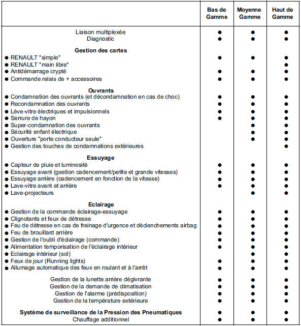
The Passenger Compartment Central Unit provides and takes part in the following functions:
- Keyless vehicle access, divided into three parts: access, protection and starting.
- Air conditioning, divided into three parts: user selection, cooling circuit and heating.
- Wiping, divided into two parts: wiper control and wiper power.
- Lighting, divided into two parts: lighting control and lighting power.
- Tyre Pressure Monitoring System (covered in chapter 35B).
Diagnosis of the body control unit is carried out using the diagnostic tool.
1 The KEYLESS ENTRY function is described as a sub-function (see the keyless entry chapter).
1.a. Access
1.a.1. Access without hands-free function:
The locking or unlocking request is made by radio-frequency exchange (transmission at 433 or 315 MHz, by pressing the card button, and reception by the antenna built into the body control unit).
The corresponding states can be viewed using states ET045 "RF frame received", ET066 "Card button press received", ET067 "Card button press recognised", by pressing the Central Locking button ET044 "CL button", or with the diagnostic tool.
The tailgate can be locked or unlocked on its own by pressing the button on the card.
Locking is confirmed by 2 flashes of the indicators.
Unlocking is confirmed by 1 flash of the indicators.
A tailgate opening request and, if the vehicle is so equipped, a rear window opening request can be viewed using states ET061 "Tailgate opening request" and ET062 "Rear window opening request".
The source of the last locking and unlocking can be viewed using states ET068 "Source of last locking" and ET069 "Source of last unlocking".
The number of cards learnt for this vehicle can be checked using parameter PR013 "Number of cards learnt" (4 maximum).
The type and vehicle assignment of the card can be checked using the specific command SC005 "Card check", and one or more cards can be assigned using the specific command SC006 "Card assignment".
- Locking with the ignition on is not possible with the card.
- Locking is not possible if one of the doors, or the tailgate, is detected as open by the body control unit.
The open or closed states of the doors as detected by the body control unit can be viewed using states ET053 "Driver door", ET042 "Passenger door", ET051 "Rear left door", ET052 "Rear right door", ET050 "Tailgate" and, if the vehicle is so equipped, ET041 "Opening rear window".
Note: The correct operation of the door switches is important, as they allow the body control unit to wake up.
After unlocking, opening a door activates timed power supply, which can be verified by the illumination of the ignition switch and the instrument panel.
The central locking button indicator lights up after locking and goes out, with the ignition off, about one minute later. Otherwise the indicator goes out after unlocking.
The operation of the central locking button indicator lighting can be checked using command AC020 "CL button indicator".
Locking can be carried out by the body control unit:
- by automatic re-locking (30 seconds after an unlocking not followed by opening a door or the tailgate).
The activation or deactivation of automatic re-locking can be checked using configuration read LC012 "Automatic re-locking" and changed using configuration CF018 "Automatic re-locking".
- by Automatic Locking When Driving (CAR function: the vehicle locks as soon as the speed signal exceeds approximately 8 km/h).
The activation or deactivation of the CAR function can be checked using state ET043 "CAR function enabled by CL".
The CAR function is activated or deactivated, with the engine running, by holding the central locking button for approximately 5 seconds. Acknowledgement is signalled by an audible alert.
WARNING:
If the central locking button is held for approximately 5 seconds with the engine stopped, the vehicle will lock itself (regardless of the state of the openings) as soon as all doors and the tailgate are detected closed by the body control unit.
Note: Unlocking can be carried out by the body control unit if the airbag control unit has detected an impact or if it is faulty (not recognised on the multiplex network, internal fault, etc.). See chapter 88C.
Depending on the country where the vehicle is used, locking/unlocking of certain doors only can be checked or configured using configuration read LC029 "Selective door opening" and configuration CF036 "Selective door opening".
The operation and power supply of the lock motors by the body control unit and the card via the card holder.
The operation and power supply of the lock motors by the body control unit can be checked using actuator commands: AC004 "Door locking", AC005 "Door unlocking" and AC006 "Driver unlocking".
1.a.2. Access with hands-free function:
Same function as "access without hands-free function" but with a different card, adding the ability to unlock and lock without any action on the card.
Unlocking is carried out by presence detection, using optical sensors located in the door handles (except the tailgate, where detection is by pressing the switch), and by a vehicle card detected following interrogation by the external antennas.
Note: Only the tailgate will be unlocked if the unlocking request is made by pressing the tailgate opening request switch.
Locking is carried out by pressing the locking buttons located on the door handles and in the tailgate badge, and by a vehicle card detected following interrogation by the external antennas.
The cabin unit configuration with hands-free function can be checked and modified using read configuration LC001 "Hands-free" and configuration CF010 "Hands-free".
Exchange principle between the key card and the antennas:
The antennas transmit (at 125 kHz) following detection by a presence sensor or pressing one of the door buttons, to check whether a key card is present in the areas covered by the exterior antennas only, with ignition off and no key card in the card reader.
The key card responds directly to the cabin unit (at 433 or 315 MHz) if it is a MEGANE II type, if it is a hands-free type and if it is learned for this vehicle.
If everything is correct, the vehicle will lock or unlock.
Note: If the key card is detected and recognized by the interior and exterior antennas, the interior antennas take priority and hands-free locking or unlocking will not work.
However, leaving a key card inside the vehicle and locking the vehicle with another key card is possible.
The cabin unit manages the power supply and the radio-frequency exchanges with the key card, from the exterior transmitting antennas.
The exchanges between the key card, in hands-free use, and the cabin unit can be viewed using state ET045 "R.F. frame received".
The cabin unit receives the lock request, in the form of a ground connection, when the lock buttons on the door and tailgate handles (button in the logo) are pressed.
Lock requests can be viewed using states ET058 "Lock button on driver's side handle", ET059 "Lock button on passenger's side handle", ET060 "Tailgate lock button on tailgate".
The cabin unit manages the power supply and the status of the door optical sensors.
The sensor power supply can be viewed using state ET054 "Optical sensors powered".
Sensor operation can be viewed using states ET055 "Front driver optical sensor", ET056 "Rear driver optical sensor", ET057 "Front/rear passenger sensor".
The optical sensor connection is backed up by a switch located in the handle, which operates by grounding as soon as the handle is pulled. It wakes up the cabin unit or replaces a faulty sensor, and makes the sensor state ACTIVE in the same way as a presence detection.
Note: After 72 hours without vehicle use, the optical sensors go into standby.
Locking takes place, + after ignition off and no key card in the card reader, by pressing the buttons on the door handles (or the logo on the tailgate) and with a vehicle key card detected by the exterior antennas only.
To check the antenna operation: Use command AC037 "Transmitting antenna diagnosis". After activation, read the faults.
If one or more antennas are detected as faulty by the cabin unit, faults concerning the antenna circuit will appear.
Note: This command diagnoses open circuits and short circuits to + 12 V of the interior and exterior antennas, but does not detect short circuits to ground.
The areas covered by the antennas can be checked using actuator commands AC032 "Exterior antennas driver side test", AC033 "Exterior antennas passenger side test", AC034 "Tailgate exterior antenna test" and ET036 "Interior antennas test" (under the "Protection" function).
Note: These commands are used to check the area covered by the antennas for key card detection.
As soon as the key card is detected, the card reader starts flashing.
These commands are used to determine the presence of a hands-free key card for Mégane II, even if it does not belong to the vehicle.
In the event of a short circuit to ground, the covered area becomes larger.
This is why the interior antennas must also be checked: in the event of a short circuit to ground, they could extend beyond the vehicle's exterior antennas and make the exterior antenna transmission ineffective.
1.a.3. Electric child safety lock (if the vehicle is equipped with it) The cabin unit controls the rear door locks to prevent them from being opened using the interior handles, and disables the operation of the rear window switches.
The switch states and activation of the electric child safety lock can be viewed using states ET089 "Electric child safety lock switch" and ET086 "Electric child safety lock", read configuration LC026 "Electric child safety lock" and configuration CF033 "Electric child safety lock".
The operation of the indicator light on the child safety switch can be checked using actuator command AC029 "Child safety indicator".
1.a.4. Super locking (if the vehicle is equipped with it and configured "WITH") The cabin unit controls the door locks to prevent unlocking using the interior handles.
Super locking is indicated by 2 flashes followed by 3 flashes of the indicators when the openings are closed.
The origin of the last activation or deactivation of super locking can be viewed using states ET088 "Super locking activation source" and ET090 "Super locking deactivation source", read configuration LC003 "Super locking" and configuration CF009 "Super locking".
1.a.5. Opening management (if the vehicle is equipped with sequential windows and a sunroof) The cabin unit manages the authorization of the windows and sunroof in the pulse-window version.
The one-touch windows are controlled by a module located in the doors.
Whether one-touch operation is enabled or disabled can be checked with status ET087 "One-touch window enable".
To enable one-touch operation, actuator test AC025 "One-touch window enable" can be used.
Note: This command can only enable one-touch operation (by grounding), not disable it.
1.b. Anti-theft protection
The passenger compartment central unit (UCH) shares control of the vehicle's anti-theft protection with other control units.
Presses of the start switch must be received by the passenger compartment central unit (UCH), as they are what request the vehicle's protection to be lifted.
Check the start switch presses using status ET070 "Start switch".
Immobiliser warning light: with the ignition off, the light flashes to indicate that the vehicle is protected.
When the ignition is switched on, the light stays on steady for 3 seconds, then goes out; the vehicle is unprotected.
If the immobiliser is not unprotected, the light will stay on steady.
Check the warning light operation using actuator test AC003 "Immobiliser warning light".
Special feature of the badge reader illumination: the badge reader lights up when the passenger compartment central unit (UCH) wakes up.
If the badge is not detected and recognised, the badge reader will start flashing.
Check the badge reader illumination using actuator test AC024 "Badge holder illumination".
Note: If the badge is not detected and recognised, a message will be displayed on the instrument panel.
Special feature of the start switch illumination: the start switch lights up when the passenger compartment central unit (UCH) wakes up, and goes out when the engine is running or when the UCH goes to sleep. It lights up again or dims when an exterior lighting request is made.
Check the start switch illumination using actuator test AC026 "Start switch illumination".
The vehicle is unprotected in the following sequence: Badge recognition by the passenger compartment central unit (UCH): after a press of the start switch, the badge is interrogated by the UCH via the badge reader (badge in the reader; the exchange takes place at 433 or 315 MHz for both the badge and the reader).
The protection system is controlled by a RENAULT badge recognition system with rolling random code. An encoded electronic module (operating without a battery), independent of the remote control or hands-free function, is built into each RENAULT badge for the vehicle.
In hands-free mode, the badge (at 433 or 315 MHz) is interrogated by the interior antennas (at 125 kHz), except when the tailgate is open or the badge battery is faulty; in those cases the badge must be placed in the badge reader.
Check that the vehicle is configured with the hands-free function using configuration read LC001 "Hands-free" and configuration CF010 "Hands-free".
As long as the badge is not recognised as present and matching this vehicle, the vehicle will remain protected.
Once the badge is recognised, the passenger compartment central unit (UCH) allows access to the power supply + accessories level.
When the ignition is switched off, if the badge is not recognised as present, two presses of the start switch are required and access to the power supply + accessories level will not be possible.
The states corresponding to the exchanges between the badge and the passenger compartment central unit (UCH) can be checked:
- ET116 "Badge code received" and ET117 "Badge code valid", badge in the reader.
- ET045 "RF frame received": badge seen by the interior antennas in hands-free mode.
The antennas can be checked using actuator tests:
- AC037 "Transmitting antenna diagnosis"; after activation, read the fault codes.
If one or more antennas are found faulty by the passenger compartment central unit (UCH), faults relating to the antenna circuit will be stored.
Note: This command checks the exterior and interior antennas, but does not detect short circuits to ground.
- AC036 "Interior antenna test"
Note: These commands are used to check the area covered by the antennas for badge detection.
As soon as the badge is detected, the badge reader starts flashing.
These commands allow a hands-free badge to be recognised on Mégane II, even if it does not belong to the vehicle.
Steering column lock:
The passenger compartment central unit (UCH) communicates with the steering column lock over the multiplexed network.
The steering column lock is permanently coded and must be assigned to this vehicle.
If the lock belongs to the vehicle, the passenger compartment central unit (UCH) requests unlocking.
The lock (unless faulty) reports its unlocked state to the passenger compartment central unit (UCH).
Once the lock is recognised as unlocked, the passenger compartment central unit (UCH) asks the Protection and Switching Unit to supply + after ignition.
Note: If the lock does not unlock or does not communicate with the passenger compartment central unit (UCH), the Protection and Switching Unit will not supply + after ignition and the immobiliser warning light will stay on steady.
The lock cannot lock if the speed signal is above 0 km/h, if the coded line is still supplied with +12 V, or if there are faults on the airbag ECU.
- ET119 "UCH request to steering column lock", ET071 "Blank steering column lock",
- ET072 "Steering column lock" and ET073 "Steering column lock sensor signal"
Immobiliser:
With + after ignition, the passenger compartment central unit (UCH) and the injection ECU compare the immobiliser code and check that it matches this vehicle.
If the check fails, the injection ECU will prevent the engine from starting.
Immobilizer deactivation can be verified using state ET046 "Immobiliser".
After the ignition is switched off, the immobilizer becomes active again as soon as the badge leaves the reader.
In hands-free use, the immobilizer becomes active again approximately 10 seconds after the ignition is switched off.
The injection ECU is supplied uncoded, see the injection chapter: 13B or 17B.
In case of failure, see fault treatment DF002 "Steering column lock", DF014 "Badge reader circuit", DF005 "Badge".
1.c. Starting
The cabin central unit shares starting control with other control units.
The starting function can only be performed if the vehicle can be fully unprotected.
Perform a forced ignition (+ after contact) to confirm the vehicle is unprotected. Starting conditions: After pressing the start switch, the cabin central unit checks the presence of the badge and the starting conditions.
- ET070 "Start switch".
With manual gearbox:
- ET047 "Brake pedal position" PRESSED.
Gear lever in neutral detected by the protection and switching unit.
or
- ET048 "Clutch pedal position" PRESSED.
With automatic gearbox:
- ET047 "Brake pedal position" PRESSED.
- ET108 "TA gear selector position" PARK or NEUTRAL.
The start request sent by the cabin central unit can be viewed using state ET110 "Request CCU to UPC or injection".
Also check the consistency of the engine state using states ET092 "Engine stopped", ET094 "Engine driven", ET091 "Engine running" and ET093 "Engine stalled".
In case of failure, see fault treatment: DF003 "Clutch switch circuit", DF004 "Brake switch circuit".
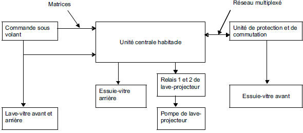
2 The WIPING function is described in sub-function
2.a. Wiper control
The cabin central unit receives the driver's request through the wiper control stalk.
Front wiper: The cabin central unit asks the protection and switching unit, via the CAN network, to supply the front wiper.
The fixed stop (park) is managed by the protection and switching unit.
The stalk has four positions (off, intermittent, low speed and high speed) and an intermittent timing ring that varies the interval between sweeps in intermittent mode.
Special case: If the front wiper is in second speed and the vehicle is stopped, the system switches to first speed.
If the front wiper is in first speed and the vehicle is stopped, the system switches to intermittent mode.
The requests made to the cabin central unit by the wiper stalk can be viewed using states: ET077 "Wiper stalk position" and ET096 "Wiper intermittent ring position".
If the vehicle is fitted with a rain sensor, see the explanation "rain and light sensor special case".
Rear wiper: The intermittent operation and supply of the rear wiper is managed by the cabin central unit.
Front wiper not in park position:
- The rear wiper starts operating as soon as reverse gear is engaged.
- At high speed, the rear wiper sweeps continuously up to 80 km/h and is delayed by 3 seconds beyond that.
The states corresponding to rear wiper operation can be viewed using states ET080 "Rear wiper request", ET097 "Rear wiper fixed stop" and ET109 "Reverse gear engaged" or ET108 "TA gear selector position", from configuration read LC019 "Rear wiper fixed stop management" and configuration CF025 "Rear wiper fixed stop management".
Washers:
The front and rear washers are controlled directly by the wiper stalk, via wired links.
These links are duplicated to the cabin central unit to allow wiping and status reading.
ET078 "Front washer request", ET079 "Rear washer request".
Headlamp washer special case
On vehicles fitted with xenon lamps, the headlamp washers, only if the headlamps are on, are controlled at the same time as the front washer.
The cabin central unit sends the command by wired link to the two headlamp washer relays, located below the protection and switching unit.
Important: If the cabin central unit cannot determine the stalk position, or cannot inform the protection and switching unit of the stalk position, the protection and switching unit will activate the front wiper at low speed (limp-home mode).
2.b. Wiper power
The cabin central unit manages the power of the rear wiper and the headlamp washers, if the vehicle is equipped with them.
Their operation can be checked using commands AC007 "Rear wiper", AC030 "Headlamp washer relay 1" and AC031 "Headlamp washer relay 2".
3 The LIGHTING function is described in sub-function
3.a. Lighting control
The cabin central unit receives the driver's request from the light stalk, the hazard warning button and, if the vehicle is equipped with it, the light sensor.
The cabin central unit asks the protection and switching unit, via the multiplexed network, to supply the position lights, low beams, high beams and front fog lights.
If the vehicle is fitted with xenon lamps, the protection and switching unit supplies the xenon lamp control units.
The low beams remain on when the high beams are activated.
The following states are displayed:
ET081 "Lighting stalk position",
ET082 "Rear fog light request",
ET085 "Hazard warning button",
ET083 "Left turn signal request",
ET084 "Right turn signal request".
If the vehicle is fitted with a light sensor, see the explanation "rain and light sensor special case".
Note:
If the cabin control unit cannot determine the position of the switch, or cannot report the switch position to the protection and switching unit, the protection unit will activate the dipped headlights.
3.b. Lighting power
The cabin control unit supplies the rear fog light (single unit), the turn signals and the interior lighting (ceiling lights and footwell/courtesy lights).
The interior lighting request can be viewed using status ET112 "Interior lighting control".
The operation of the lights supplied by the cabin control unit can be checked using actuator commands AC009 "Rear fog lights", AC022 "Left turn signal", AC023 "Right turn signal", AC021 "Ceiling light activation" and AC027 "Footwell/courtesy light".
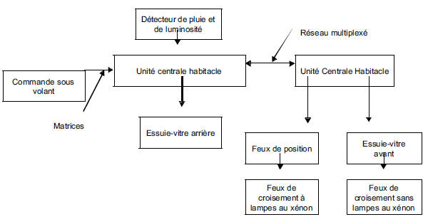
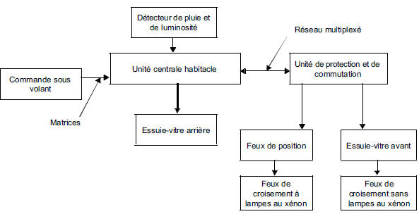
SPECIAL FEATURE: RAIN AND LIGHT SENSOR (if fitted to the vehicle).
The rain and light sensor is a single sensor, connected by a single link to the cabin control unit. This sensor is mounted on the windscreen.
The rain sensor automatically activates the front windscreen wiper and controls the wiping speed according to the amount of water on the windscreen.
The sensor is activated by moving the wiper switch to the intermittent position.
Automatic operation by the rain sensor is inhibited after the ignition is switched off.
To reactivate operation at the next ignition switch-on, move the wiper switch to the off position, then back to the intermittent position.
On a vehicle fitted with a rain sensor, with automatic detection activated and no rain, the rear windscreen wiper will start if reverse gear is engaged.
Note: On vehicles without a rain sensor, the "Auto" position on the wiper switch replaces the intermittent speed, and the ring is then used to adjust the rain sensor sensitivity.
Use status ET118 "Rain sensor sensitivity ring position" instead of status ET096.
The rain sensor operation can be viewed using status ET114 "Wiper request by rain sensor" and configuration read LC006 "Rain sensor". The configuration can be changed using command CF012 "Rain sensor".
The light sensor automatically switches on the parking lights and dipped headlights when the vehicle is in a dark place (tunnel, night, dark weather conditions, etc.).
The light sensor status can be viewed using ET115 "Light sensor lighting request" and configuration read LC007 "Light sensor". The configuration can be changed using command CF013 "Light sensor".
4 The AIR CONDITIONING function is described in a sub-function.
The air conditioning type can be viewed using configuration read LC013 "Air conditioning type" and configured using command CF019 "Air conditioning type".
4.a. User selection (manual air conditioning only)
The cabin control unit receives the following information from the air conditioning control panel via hardwired links: the air conditioning request, the electric rear window defroster request, and the cabin blower operation status.
The cabin control unit sends a request to the protection and switching unit to activate the electric rear window defroster.
The cabin control unit sends a request to the injection system to engage the air conditioning compressor.
The following statuses can be viewed:
- ET029 "Air conditioning button",
- ET028 "Rear window heater button",
- ET015 "Cabin blower".
The operation of the air conditioning request and electric rear window defroster button indicators can be checked using actuator commands AC015 "Air conditioning button indicator" and AC019 "Rear window defroster indicator".
4.b. Heating
The cabin control unit controls the Cabin Heating Resistors (CHR) by driving power relays according to the cabin ventilation demand, engine coolant temperature, outside air temperature, electrical load balance, engine load and, on convertible versions, whether the roof is open.
The statuses produced by the cabin control unit can be viewed:
- PR001 "Battery voltage",
- PR002 "Outside air temperature",
- ET015 "Cabin blower" only with manual air conditioning,
- ET017 "Number of CHR required",
- ET018 "Number of CHR allowed by alternator" alternator load rate,
- ET019 "Number of CHR allowed by injection",
- ET020 "Number of CHR commanded"
- ET021 "CHR 1 command",
- ET022 "CHR 2 command",
- ET031 "Fast idle request for CHR",
- ET091 "Engine running",
- ET025 "Retractable roof" convertible version only,
- ET026 "Rear window heater".
Relay 1 controls a cabin heating resistor block consisting of one resistor.
Relay 2 controls a cabin heating resistor block consisting of two resistors.
The operation of the cabin heating resistors can be checked using actuator commands AC016 "CHR 1 relay" and AC017 "CHR 2 relay".
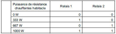
Configuration read LC027 "Additional heating power available" can be viewed.
4.c. Cold loop
The cabin control unit requests compressor engagement from the injection system over the multiplexed network, based on the outside air temperature, the cabin blower activation information, and whether the engine is running.
The following statuses and parameters can be viewed: ET030 "Air conditioning request 2", ET091 "Engine running", ET015 "Cabin blower" and PR002 "Outside air temperature".
Test yourself
A quick Renault Megane quiz: every answer comes with an explanation and a link to the manual page.