Fault interpretation
| DF001 PRESENT | BODY CONTROL MODULE 1.FAULT: internal electronic fault |
INSTRUCTIONS
Conditions for applying the diagnosis on a stored fault: Lock/unlock the vehicle by pressing the button on the badge.
If the fault becomes present, carry out this diagnosis.
Particularities: If a fault concerning the steering column lock is present or stored, deal with it as a priority.
Contact your techline.
AFTER REPAIR
Carry out a new system diagnosis.
Clear the stored faults.
Deal with any other faults.
| DF002 PRESENT | STEERING COLUMN LOCK 1.FAULT: Steering column lock internal electronic failure |
INSTRUCTIONS
Priorities when handling multiple faults: Apply the handling of fault DF029 "Steering column lock circuit" first if it is present.
Particularities: Lock-unlock the vehicle, open the driver's door.
Contact your techline.
AFTER REPAIR
Carry out a new system diagnosis.
Clear the stored faults.
Deal with any other faults.
| DF003 PRESENT OR STORED | CLUTCH SWITCH CIRCUIT CC.0: Short circuit to earth |
INSTRUCTIONS
Condition for applying the diagnosis on a stored fault: The fault becomes present following: a road test with V > 40 km/h.
CC.0
INSTRUCTIONS
Nothing to report.
| Check the condition and connection of the green 2-way connector of the clutch switch (pushed-back, broken or corroded pins, etc.). Repair if necessary. |
| Check the condition and connection of the blue 40-way PE1 connector of the Body Control Module (pushed-back, broken or corroded pins, etc.). Repair if necessary. |
| Ensure the insulation of the wiring to earth: Switch pin 1 → pin 5 of the 40-way PE1 connector of the Body Control Module Repair if necessary. |
| If the wiring is correct, replace the switch. |
| If the fault persists, contact the techline. |
AFTER REPAIR
Carry out a new system diagnosis.
Clear the stored faults.
Deal with any other faults.
CO.1
INSTRUCTIONS
Nothing to report.
| Check the condition and connection of the green 2-way connector of the clutch switch (pushed-back, broken or corroded pins, etc.). Repair if necessary. |
| Check the condition and connection of the blue 40-way PE1 connector of the Body Control Module (pushed-back, broken or corroded pins, etc.). Repair if necessary. |
| Ensure the insulation from +12 V and the continuity of the wiring: Switch pin 1 → pin 5 of the 40-way PE1 connector of the Body Control Module |
| Ensure the presence of vehicle earth on pin 2 of the switch. Repair if necessary. |
| If the wiring is correct and earth is present, replace the switch. |
| If the fault persists, contact the techline. |
AFTER REPAIR
Carry out a new system diagnosis.
Clear the stored faults.
Deal with any other faults.
| DF004 PRESENT OR STORED | BRAKE SWITCH CIRCUIT |
INSTRUCTIONS
Conditions for applying the diagnosis on a stored fault: The fault becomes present following a succession of 10 presses of more than 1 second. Note: The fault may prevent the cruise control/speed limiter from operating.
Refer to the handling of status ET047 "Brake pedal position" in the "Starting" sub-function.AFTER REPAIR
Carry out a new system diagnosis.
Clear the stored faults.
Deal with any other faults.
| DF005 PRESENT OR STORED | BADGE FAULT: Badge battery low |
FAULT
INSTRUCTIONS
Conditions for applying the diagnosis on a stored fault: Press one of the buttons on the badge and check whether the fault becomes present.
Carry out the test with another badge belonging to the vehicle.
| Check the badge battery. Replace the battery if necessary. |
| If the fault persists, complete the diagnostic sheet and contact your techline. |
AFTER REPAIR
Carry out a new system diagnosis.
Clear the stored faults.
Deal with any other faults.
| DF006 DF007 DF008 DF009 PRESENT | FRONT LEFT VALVE SENSOR FRONT RIGHT VALVE SENSOR REAR RIGHT VALVE SENSOR REAR LEFT VALVE SENSOR 1.DEF: Internal electronic fault |
INSTRUCTIONS
Special notes: Any work involving replacement of a valve or removal of a tyre requires full knowledge of the precautions defined in Repair Manual 364, chapter 35.
Before any work, make sure all fitted wheels have a tyre pressure monitoring valve, and that the spare wheel is not fitted on either axle.
For faults DF006 to DF009, if the fault is present from the first kilometres, carry out a learning of the 4 valve(s) again. If the learning fails, replace the valve concerned following the method described in the repair manual (Repair manual 364 chapter 35B).Check that no wheel has a rubber valve. If so, replace it with a wheel fitted with a valve incorporating a sensor, then carry out a road test. If the fault is still present, perform a learning procedure for all 4 valves. If the fault persists, replace the valve.
The correspondence between fault numbers and the valve concerned is described below:- DF006 = Front left valve sensor
- DF007 = Front right valve sensor
- DF008 = Rear right valve sensor
- DF009 = Rear left valve sensor
When a sensor is replaced, carry out a learning of the codes of the four valves using procedure SC002 "Learning the codes of the four valves" described in the "Repair" section of this chapter.
AFTER REPAIR
Deal with any other faults.
Switch off the ignition and carry out a road test followed by a check with the diagnostic tool.
| DF010 PRESENT OR STORED | STEERING WHEEL CONTROL UNIT CIRCUIT 1.DEF: Fault detected on the link between the steering wheel control unit and the Cabin Central Unit |
INSTRUCTIONS
Condition for applying the diagnosis on a stored fault: If the fault becomes present following an action on the control, then carry out this diagnosis.
1.DEF
INSTRUCTIONS
Without.
| Check the condition and connection of the 40-way PE2 connector on the Cabin Central Unit (pins pushed back, broken or corroded). Repair it if necessary. |
| Check the condition and connection of the 12-way black connector on the steering wheel control (pins pushed back, broken or corroded). Repair it if necessary. |
| Check the insulation and continuity of the following links: 12-way black connector to 40-way PE2 connector on the Cabin Central Unit. pin 3 → pin 14, Repair if necessary. |
| If the links are correct, replace the steering wheel control if necessary. |
| Contact your techline. |
2.DEF
INSTRUCTIONS
Without.
Replace the steering wheel control unit.
AFTER REPAIR
Carry out a new system diagnosis.
Clear the stored faults.
Deal with any other faults.
| DF011 PRESENT OR STORED | RAIN/LIGHT SENSOR CIRCUIT 1.DEF: Communication disturbed |
INSTRUCTIONS
Condition for applying the diagnosis on a stored fault: Activate the automatic wiper system and automatic headlight system, then cover the sensor and/or put water on it.
If the fault becomes present, then carry out this diagnosis.
1.DEF
INSTRUCTIONS
| Check the condition and connection of the sensor power supply fuse in the Cabin Fuse and Relay Box, position 2S. Replace it if necessary. |
| Check the condition and connection of the sensor's 3-way black connector (pins pushed back, broken or corroded, etc.). Repair if necessary. |
| Check for ground on pin 3 of the sensor. Repair if necessary. |
| Check for +12 V on pin 1 of the rain/light sensor. If conforming, replace the sensor. |
| Check the condition and connection of the 40-way PE2 connector on the Cabin Central Unit (pins pushed back, broken or corroded, etc.). Repair if necessary. |
| Check the continuity and insulation of the following link: sensor pin 2 → pin 2 of the PE2 connector on the Cabin Central Unit. Repair if necessary. |
| If the fault persists, contact Techline. |
2.DEF
INSTRUCTIONS
If fault is present.
Replace the sensor.
AFTER REPAIR
Carry out a new system diagnosis.
Clear the stored faults.
Deal with any other faults.
| DF012 PRESENT OR STORED | RIGHT TURN SIGNAL CIRCUIT CC.0: Short to ground |
INSTRUCTIONS
Condition for applying the diagnosis on a stored fault: If the fault becomes present following an action on the right turn signal control, then carry out this diagnosis.
Special note: The fault is stored following a bulb replacement.
| Check the bulbs. Replace them if necessary. |
| Check the condition and connection of the connectors of the left headlight, left side repeater and left rear light. Repair if necessary. |
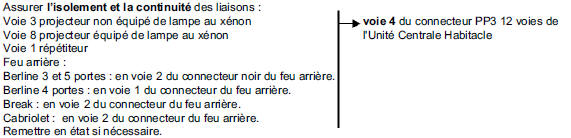
| Check for ground on the faulty component: Pin 1 headlight not fitted with xenon lamp / Pins 1 and 4 headlight fitted with xenon lamp; Pin 2 side repeater. Rear light: 3- and 5-door saloon: on pin 3 of the black rear light connector. 4-door saloon: on pin 2 of the rear light connector. Estate: on pin 3 of the rear light connector. Convertible: on pin 3 of the rear light connector. Repair if necessary. |
| With the control activated, check for +12 V on the faulty component: Pin 3 headlight not fitted with xenon lamp / Pin 8 headlight fitted with xenon lamp; Pin 1 side repeater. Rear light: 3- and 5-door saloon: on pin 2 of the black rear light connector. 4-door saloon: on pin 1 of the rear light connector. Estate: on pin 2 of the rear light connector. Convertible: on pin 2 of the rear light connector. If conforming, check the bulbs again and if still non-conforming, replace the rear light(s). |
| Check the condition and connection of the PP3 connector on the Cabin Central Unit. Repair if necessary. |
 |
| If the problem persists, contact Techline. |
AFTER REPAIR
Carry out a new system diagnosis.
Clear the stored faults.
Deal with any other faults.
| DF013 PRESENT OR STORED | LEFT TURN SIGNAL CIRCUIT CC.0: Short to ground |
INSTRUCTIONS
Condition for applying the diagnosis on a stored fault: If the fault becomes present following an action on the left turn signal control, then carry out this diagnosis.
Special note: The fault is stored following a bulb replacement.
| Check the bulbs. Replace them if necessary. |
| Check the condition and connection of the connectors of the right headlight, right side repeater and right rear light. Repair if necessary. |
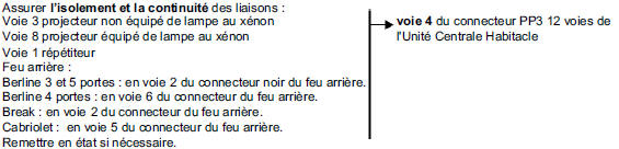
| Check for ground on the faulty component: Pin 1 headlight not fitted with xenon lamp / Pins 1 and 4 headlight fitted with xenon lamp; Pin 2 side repeater. Rear light: 3- and 5-door saloon: on pin 3 of the black rear light connector. 4-door saloon: on pin 5 of the rear light connector. Estate: on pin 3 of the rear light connector. Convertible: on pin 4 of the rear light connector. Repair if necessary. |
| With the control activated, check for +12 V on the faulty component: Pin 3 headlight not fitted with xenon lamp / Pin 8 headlight fitted with xenon lamp; Pin 1 side repeater. Rear light: 3- and 5-door saloon: on pin 2 of the black rear light connector. 4-door saloon: on pin 1 of the rear light connector. Estate: on pin 2 of the rear light connector. Convertible: on pin 5 of the rear light connector. If compliant, check the bulbs again. If still non-compliant, replace the rear light(s). |
| Check the condition and connection of the PP3 connector on the Cabin Central Unit. Repair if necessary. |
 |
| If the problem persists, contact Techline. |
AFTER REPAIR
Carry out a new system diagnosis.
Clear the stored faults.
Deal with any other faults.
| DF014 PRESENT OR STORED | CARD READER CIRCUIT CC.0: Short to ground |
INSTRUCTIONS
Condition for applying the diagnosis on a stored fault: Place the card in the reader, then switch the ignition off and back on.
If the fault becomes present, then carry out this diagnosis.
FAULT
INSTRUCTIONS
Nothing to report
| Check the condition and connection of the 8-way black card reader connector (pins pushed back, broken, corroded, etc.). Repair if necessary. |
| Check the condition and connection of the 40-way black PE2 connector and the 40-way blue PE1 connector on the Passenger Compartment Central Unit (pins pushed back, broken, corroded, etc.). Repair if necessary. |
| Check for 12 V on pin 3 of the card reader. Repair if necessary. |
| Check the continuity and insulation to ground of the following links: Card reader pin 4 → pin 39 of the 40-way black PE2 connector on the Passenger Compartment Central Unit Repair if necessary. |
| Replace the card reader if necessary. |
| IF the fault persists, contact your techline. |
AFTER REPAIR
Carry out a new system diagnosis.
Clear the stored faults.
Deal with any other faults.
FAULT
INSTRUCTIONS
Without.
Replace the card reader.
AFTER REPAIR
Carry out a new system diagnosis.
Clear the stored faults.
Deal with any other faults.
| DF015 PRESENT OR STORED | OPTICAL SENSOR CIRCUIT CC.0: Short to ground |
INSTRUCTIONS
Condition for applying the diagnosis on a stored fault: Lock the vehicle and pass your hand over each door handle.
If the fault becomes present, then carry out this diagnosis.
Note: Hands-free systems only.
| Check the sensor states to determine which sensor has the short circuit. ET055 "Driver front optical sensor", Each state must change to ACTIVE. |
| If a state is INACTIVE: Check for 12 V on pin 3 of the sensor(s). Repair if necessary. |
| Check the insulation and continuity of the following links: Driver front sensor pin 1 → pin 21 of the 40-way grey connector on the Passenger Compartment Central Unit. Repair if necessary. |
| If the links are correct and the power supply is present, replace the faulty sensor. |
| If the fault persists, contact your techline. |
AFTER REPAIR
Carry out a new system diagnosis.
Clear the stored faults.
Deal with any other faults.
| DF016 DF017 PRESENT | AT LEAST 2 IDENTICAL CODES IN THE SUMMER SET AT LEAST 2 IDENTICAL CODES IN THE WINTER SET |
INSTRUCTIONS
Notes: Any work involving replacement of a valve or removal of a tyre requires full knowledge of the precautions defined in MR364, chapter 35.
Before any work, make sure all fitted wheels have a tyre pressure monitoring valve, and that the spare wheel is not fitted on the same axle.
| Fault DF016 "At least 2 identical codes / summer set" appears when, in the summer wheel set, at least two valve codes are identical (incorrect learning of the codes of the four valves). In this case, repeat the learning of the four valve codes using procedure SC002 "Learning the codes of the four valves" described in the "Repair" section of this note. |
| Fault DF017 "At least 2 identical codes / winter set" appears when, in the winter wheel set, at least two valve codes are identical (incorrect learning of the codes of the four valves). In this case, repeat the learning of the four valve codes using procedure SC002 "Learning the codes of the four valves" described in the "Repair" section of this note. |
AFTER REPAIR
Deal with any other faults.
Switch off the ignition and carry out a road test, followed by a check with the diagnostic tool.
| DF018 DF019 PRESENT | 4-CODE LEARNING IN SUMMER SET NOT PERFORMED 4-CODE LEARNING IN WINTER SET NOT PERFORMED |
INSTRUCTIONS
Notes: Any work involving replacement of a valve or removal of a tyre requires full knowledge of the precautions defined in MR 364, chapter 35.
Before any work, make sure all fitted wheels have a tyre pressure monitoring valve, and that the spare wheel is not fitted.
Fault DF018 "4 summer wheel set codes learning not performed" is present if the Body Control Module has not learned a valve code for the summer wheel set (following a replacement of the sensors or of the Body Control Module).Fault DF019 "4-code learning in winter set not performed" is present if the Passenger Compartment Central Unit has not learned a valve code for the winter wheel set and the winter wheel set is selected.
In the status menu, check the type of wheel set stored (summer or winter).
In the status menu, for the stored wheel type, check the assigned valve codes.
Perform learning of the four valve codes using procedure SC002 "Learning the codes of the four valves" described in the "Repair" section of this note.
AFTER REPAIR
Deal with any other faults.
Switch off the ignition and carry out a road test followed by a check with the diagnostic tool.
| DF020 PRESENT OR STORED | FRONT INTERIOR ANTENNA CIRCUIT CO: Open circuit |
INSTRUCTIONS
Condition for applying the diagnosis on a stored fault: Activate command AC037 "Transmitter antenna diagnosis"; if the fault becomes present, then carry out this diagnosis.
| Check the condition and connection of the 3-way black connector (pins pushed back, broken, etc.). Repair if necessary. |
| Check the condition and connection of the 40-way PE2 connector on the Passenger Compartment Central Unit (pins pushed back, broken, etc.). Repair if necessary. |
| Check the insulation and continuity of the following links: 3-way connector pin 1 → pin 25 of the 40-way PE3 connector on the Passenger Compartment Central Unit Repair if necessary. |
| Replace the antenna if necessary. |
| If the problem persists, contact Techline. |
AFTER REPAIR
Carry out a new system diagnosis.
Clear the stored faults.
Deal with any other faults.
| DF021 PRESENT OR STORED | REAR INTERIOR ANTENNA CIRCUIT CO: Open circuit |
INSTRUCTIONS
Condition for applying the diagnosis on a stored fault: Activate command AC037 "Transmitter antenna diagnosis"; if the fault becomes present, then carry out this diagnosis.
| Check the condition and connection of the 3-way black connector (pins pushed back, broken, etc.). Repair if necessary. |
| Check the condition and connection of the 40-way PE2 connector on the Passenger Compartment Central Unit (pins pushed back, broken, etc.). Repair if necessary. |
| Check the insulation and continuity of the following links: 3-way connector pin 1 → pin 35 of the 40-way PE3 connector of the Passenger Compartment Central Unit Repair if necessary. |
| Replace the antenna if necessary. |
| If the problem persists, contact Techline. |
AFTER REPAIR
Carry out a new system diagnosis.
Clear the stored faults.
Deal with any other faults.
| DF022 PRESENT OR STORED | INTERIOR CENTRAL ANTENNA CIRCUIT CO: Open circuit |
INSTRUCTIONS
Application condition for diagnosis of stored fault: Activate command AC037 "Transmitter antenna diagnosis"; if the fault becomes present, then carry out this diagnosis.
| Check the condition and connection of the 3-way black connector (pins pushed back, broken, etc.). Repair if necessary. |
| Check the condition and connection of the 40-way PE2 connector on the Passenger Compartment Central Unit (pins pushed back, broken, etc.). Repair if necessary. |
| Check the insulation and continuity of the following links: 3-way connector pin 1 → pin 26 of the 40-way PE3 connector of the Passenger Compartment Central Unit Repair if necessary. |
| Replace the antenna if necessary. |
| If the problem persists, contact Techline. |
AFTER REPAIR
Carry out a new system diagnosis.
Clear the stored faults.
Deal with any other faults.
| DF023 PRESENT OR STORED | DRIVER FRONT DOOR EXTERIOR ANTENNA CO: Open circuit |
INSTRUCTIONS
Application condition for diagnosis of stored fault: Activate command AC037 "Transmitter antenna diagnosis"; if the fault becomes present, then carry out this diagnosis
| Check the condition and connection of the 4-way black connector (bent or broken terminal tabs, etc.). Repair if necessary. |
| Check the condition and connection of the 40-way PE2 connector on the Passenger Compartment Central Unit (pins pushed back, broken, etc.). Repair if necessary. |
| Check the insulation and continuity of the following links: 4-way connector pin 1 → pin 27 of the 40-way PE3 connector of the Passenger Compartment Central Unit Repair if necessary. |
| Replace the antenna if necessary. |
| If the problem persists, contact Techline. |
AFTER REPAIR
Carry out a new system diagnosis.
Clear the stored faults.
Deal with any other faults.
| DF024 PRESENT OR STORED | PASSENGER FRONT DOOR EXTERIOR ANTENNA CO: Open circuit |
INSTRUCTIONS
Condition for applying the diagnosis on a stored fault: Activate command AC037 "Transmitter antenna diagnosis"; if the fault becomes present, then carry out this diagnosis.
| Check the condition and connection of the 4-way black connector (bent or broken terminal tabs, etc.). Repair if necessary. |
| Check the condition and connection of the 40-way PE2 connector on the Passenger Compartment Central Unit (pins pushed back, broken, etc.). Repair if necessary. |
| Check the insulation and continuity of the following links: 4-way connector pin 1 → pin 31 of the 40-way PE3 connector of the Passenger Compartment Central Unit Repair if necessary. |
| Replace the antenna if necessary. |
| If the problem persists, contact Techline. |
AFTER REPAIR
Carry out a new system diagnosis.
Clear the stored faults.
Deal with any other faults.
| DF025 PRESENT OR STORED | DRIVER REAR DOOR EXTERIOR ANTENNA CO: Open circuit |
INSTRUCTIONS
Condition for applying the diagnosis on a stored fault: Activate command AC037 "Transmitter antenna diagnosis"; if the fault becomes present, then carry out this diagnosis.
| Check the condition and connection of the 4-way black connector (bent or broken terminal tabs, etc.). Repair if necessary. |
| Check the condition and connection of the 40-way PE2 connector on the Passenger Compartment Central Unit (pins pushed back, broken, etc.). Repair if necessary. |
| Check the insulation and continuity of the following links: 4-way connector pin 1 → pin 28 of the 40-way PE3 connector of the Passenger Compartment Central Unit Repair if necessary. |
| Replace the antenna if necessary. |
| If the problem persists, contact Techline. |
AFTER REPAIR
Carry out a new system diagnosis.
Clear the stored faults.
Deal with any other faults.
| DF026 PRESENT OR STORED | PASSENGER REAR DOOR EXTERIOR ANTENNA CO: Open circuit |
INSTRUCTIONS
Application condition for diagnosis of stored fault: Activate command AC037 "Transmitter antenna diagnosis"; if the fault becomes present, then carry out this diagnosis.
| Check the condition and connection of the 4-way black connector (bent or broken terminal tabs, etc.). Repair if necessary. |
| Check the condition and connection of the 40-way PE2 connector on the Passenger Compartment Central Unit (pins pushed back, broken, etc.). Repair if necessary. |
| Check the insulation and continuity of the following links: 4-way connector pin 1 → pin 32 of the 40-way PE3 connector of the Passenger Compartment Central Unit Repair if necessary. |
| Replace the antenna if necessary. |
| If the problem persists, contact Techline. |
AFTER REPAIR
Carry out a new system diagnosis.
Clear the stored faults.
Carry out diagnosis of any other faults.
| DF027 PRESENT OR STORED | OUTSIDE TEMPERATURE SENSOR CIRCUIT CC.1: Short circuit to + 12 V |
INSTRUCTIONS
Application condition for diagnosis of stored fault: The fault reappears as stored following:
- clearing of the fault.
| Check whether the right-hand mirror is fitted with a temperature sensor. If NO, vehicle not equipped. If YES, carry out the following diagnosis. |
| Check the green 2-way temperature sensor connector (bent or pushed-back terminal tabs, corrosion, broken parts). Repair if necessary. |
| Check the black 40-way PE2 connector of the Passenger Compartment Central Unit (bent or pushed-back terminal tabs, corrosion, broken parts). Repair if necessary. |
| Check the continuity and insulation of the links: Temperature sensor pin 1 → pin 3 of the black 40-way connector of the Passenger Compartment Central Unit. Repair if necessary. Check the sensor resistance between pins 1 and 2. Approximate temperature (°C) Sensor resistance (Ω) |
| Replace the sensor if necessary. |
| If the problem persists, contact the techline. |
AFTER REPAIR
Carry out a new system diagnosis.
Clear the stored faults.
Deal with any other faults.
| DF029 PRESENT | STEERING COLUMN LOCK CIRCUIT CC.1: Short circuit to + 12 V |
INSTRUCTIONS
Nothing to report
Special note: Lock and unlock the vehicle; check the lock power supply within 5 minutes after a door has been opened.
CC.1. SHORT CIRCUIT to + 12 V
INSTRUCTIONS
Nothing to report
| Check the condition and connection of the 6-way steering column lock connector. Repair if necessary. |
| Check the condition and connection of the PE2 and PP2 connectors of the Passenger Compartment Central Unit and the PEH connector of the Protection and Switching Unit (bent or broken terminal tabs, etc.). Repair if necessary. |
| Check the insulation and continuity of the following links: Steering column lock pin 3 → pin 10 of the PE2 connector of the Passenger Compartment Central Unit Repair if necessary. |
| If the problem persists, contact your techline. |
AFTER REPAIR
Carry out a new system diagnosis.
Clear the stored faults.
Deal with any other faults.
1.DEF
INSTRUCTIONS
Nothing to report
| Check the condition and connection of the 6-way steering column lock connector. Repair if necessary. |
| Check the condition and connection of the PP2 and PE2 connectors of the Passenger Compartment Central Unit (bent or broken terminal tabs, etc.). Repair if necessary. |
| Check for + 12 V on pin 2 of the steering column lock. |
| Check the continuity of the link between pin 1 of the connector and vehicle body ground. Repair if necessary. |
| Check the insulation and continuity of the following links: Steering column lock pin 3 → pin 10 of the PE2 connector of the Passenger Compartment Central Unit Repair if necessary. |
| If the problem persists, contact your techline. |
AFTER REPAIR
Carry out a new system diagnosis.
Clear the stored faults.
Deal with any other faults.
2.DEF
INSTRUCTIONS
Nothing to report
| Check the condition and connection of the 6-way steering column lock connector (bent or broken terminal tabs, etc.). Repair if necessary. |
| Check the condition and connection of the PE2 connector of the Passenger Compartment Central Unit (bent or broken terminal tabs, etc.). Repair if necessary. |
| Check the insulation and continuity of the link between pin 1 of the connector and vehicle body ground. Repair if necessary. |
| Check the continuity of the link between pin 1 of the connector and vehicle body ground. Repair if necessary. |
| Check the insulation and continuity of the following links: Steering column lock pin 3 → pin 10 of the PE2 connector of the Passenger Compartment Central Unit Repair if necessary. |
| If the problem persists, contact your techline. |
AFTER REPAIR
Carry out a new system diagnosis.
Clear the stored faults.
Deal with any other faults.
3.DEF
INSTRUCTIONS
Nothing to report
Check the battery voltage and carry out a charging circuit check (overvoltage).Locking or unlocking possible if voltage is between 9 V < Voltage < 16 V. Unlocking impossible if voltage > 16 V.
AFTER REPAIR
Carry out a new system diagnosis.
Clear the stored faults.
Address any other faults present.
4.DEF
INSTRUCTIONS
Nothing to report
| Check the condition and connection of the 6-way steering column lock connector (bent or broken terminal tabs, etc.). Repair if necessary. |
| Check the condition and connection of connector PE1 on the Cabin Central Unit (bent or broken tabs, etc.). Repair if necessary. |
| Check continuity and insulation of the link: Steering column lock pin 4 → pin 1 of 12-way connector PP1 on the Cabin Central Unit Repair if necessary. |
| If the problem persists, contact your techline. |
AFTER REPAIR
Carry out a new system diagnosis.
Clear the stored faults.
Deal with any other faults.
5.DEF
INSTRUCTIONS
Nothing to report
| Check the condition and connection of the 6-way steering column lock connector (bent or broken terminal tabs, etc.). Repair if necessary. |
| Check the condition and connection of connector PE1 on the Cabin Central Unit (bent or broken tabs, etc.). Repair if necessary. |
| Check continuity and insulation of the link: Steering column lock pin 4 → pin 1 of 12-way connector PP1 on the Cabin Central Unit Repair if necessary. |
| If the problem persists, contact your techline. |
AFTER REPAIR
Carry out a new system diagnosis.
Clear the stored faults.
Deal with any other faults.
6.DEF
INSTRUCTIONS
Nothing to report
| Check the condition and connection of the 6-way steering column lock connector (bent or broken terminal tabs, etc.). Repair if necessary. |
| Check the condition and connection of connector PE1 on the Cabin Central Unit (bent or broken tabs, etc.). Repair if necessary. |
| Check continuity and insulation of the link: Steering column lock pin 4 → pin 1 of 12-way connector PE1 on the Cabin Central Unit Repair if necessary. |
| If the problem persists, contact your techline. |
AFTER REPAIR
Carry out a new system diagnosis.
Clear the stored faults.
Carry out diagnosis of any other faults.
| DF030 PRESENT | ANTI-LOCKING LINE CO: Open circuit |
INSTRUCTIONS
Nothing to report
CO.1
INSTRUCTIONS
| Check the condition and connection of the 6-way black steering column lock connector (bent or broken tabs). Repair if necessary. |
| Check the condition and presence of fuse 5D on the Protection and Switching Unit. Repair if necessary. |
| Check the condition and connection of connector PEH on the Protection and Switching Unit (bent or broken tabs, etc.). Repair if necessary. |
| Check insulation and continuity of the following link: Steering column lock pin 5 → pin 1 of 12-way connector PEH on the Protection and Switching Unit Repair if necessary. |
| If the problem persists, contact your techline. |
AFTER REPAIR
Carry out a new system diagnosis.
Clear the stored faults.
Deal with any other faults.
| DF031 PRESENT OR STORED | IMPULSE WINDOW LIFT LINK CC.1: Short circuit to +12 V |
INSTRUCTIONS
Condition for applying diagnosis on stored fault: If the fault becomes present following an action on the impulse window lift, then carry out this diagnosis.
Note: If the vehicle is not fitted with impulse window lifts, ignore this fault.
| Check the condition and connection of the 6-way window lift connectors (bent or broken tabs, etc.). Repair if necessary. |
| Check the condition and connection of the PE2 connector of the Passenger Compartment Central Unit (bent or broken terminal tabs, etc.). Repair if necessary. |
| Check insulation and continuity of the link: 40-way connector PE2 pin 7 → pin 6 of window lift connector Repair if necessary. |
| If the fault persists, contact the techline. |
AFTER REPAIR
Carry out a new system diagnosis.
Clear the stored faults.
Carry out diagnosis of any other faults.
| DF032 PRESENT OR STORED | REAR BOOT EXTERNAL ANTENNA CIRCUIT CO.1: Open circuit or short circuit to +12 V |
INSTRUCTIONS
Condition for applying the diagnosis on a stored fault: Activate command AC037 "Transmitter antenna diagnosis"; if the fault becomes present, then carry out this diagnosis.
| Check the condition and connection of the 4-way black connector (bent or broken terminal tabs, etc.). Repair if necessary. |
| Check the condition and connection of the 40-way PE2 connector on the Passenger Compartment Central Unit (pins pushed back, broken, etc.). Repair if necessary. |
| Check the insulation and continuity of the following links: 4-way connector pin 1 → pin 29 of 40-way connector PE3 on the Cabin Central Unit Repair if necessary. |
| Replace the antenna if necessary. |
| If the problem persists, contact Techline. |
AFTER REPAIR
Carry out a new system diagnosis.
Clear the stored faults.
Carry out diagnosis of any other faults.
| DF033 PRESENT OR STORED | DRIVER SIDE EXTERNAL ANTENNA(S) CO.1: Open circuit or short circuit to +12 V |
INSTRUCTIONS
Condition for applying the diagnosis on a stored fault: Activate command AC037 "Transmitter antenna diagnosis"; if the fault becomes present, then carry out this diagnosis.
Front door
| Check the condition and connection of the 4-way black connector (bent or broken terminal tabs, etc.). Repair if necessary. |
| Check the condition and connection of the 40-way PE2 connector on the Passenger Compartment Central Unit (pins pushed back, broken, etc.). Repair if necessary. |
| Check insulation of the following links: 4-way connector pin 1 → pin 27 of the 40-way PE3 connector of the Passenger Compartment Central Unit Repair if necessary. |
| Replace the antenna if necessary. |
| If the problem persists, contact Techline. |
AFTER REPAIR
Carry out a new system diagnosis.
Clear the stored faults.
Deal with any other faults.
Rear door
| Check the condition and connection of the 4-way black connector (bent or broken tabs, etc.). Repair if necessary. |
| Check the condition and connection of the 40-way PE2 connector on the Passenger Compartment Central Unit (pins pushed back, broken, etc.). Repair if necessary. |
| Check insulation of the following links: 4-way connector pin 1 → pin 28 of the 40-way PE3 connector of the Passenger Compartment Central Unit Repair if necessary. |
| Replace the antenna if necessary. |
| If the problem persists, contact Techline. |
AFTER REPAIR
Carry out a new system diagnosis.
Clear the stored faults.
Deal with any other faults.
| DF034 PRESENT OR STORED | PASSENGER SIDE EXTERNAL ANTENNA(S) CO.1: Open circuit or short circuit to +12 V |
INSTRUCTIONS
Application condition for diagnosis of stored fault: Activate command AC037 "Transmitter antenna diagnosis"; if the fault becomes present, then carry out this diagnosis.
Front door
| Check the condition and connection of the 4-way black connector (bent or broken terminal tabs, etc.). Repair if necessary. |
| Check the condition and connection of the 40-way PE2 connector on the Passenger Compartment Central Unit (pins pushed back, broken, etc.). Repair if necessary. |
| Check insulation to ground of the following links: 4-way connector pin 1 → pin 31 of 40-way connector PE3 on the Cabin Central Unit |
Test yourself
A quick Renault Megane quiz: every answer comes with an explanation and a link to the manual page.