Transmission / transaxle
Clutch installation
In this manual: Transmission / transaxle
18steps
~108min
4/5difficulty
Done 0 of 18
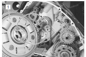
- Install the primary driven gear assembly (1).
- if it is difficult to install the primary driven gear, rotate the crankshaft.
- Be sure to engage the oil pump drive sprocket with the primary driven gear.
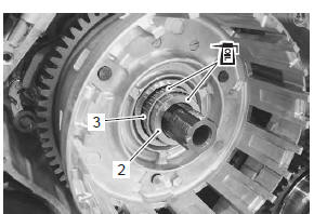
- Install the spacer (2) and bearing (3), and apply engine oil to them.
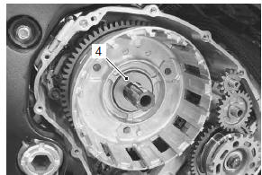
- Install the thrust washer (4).
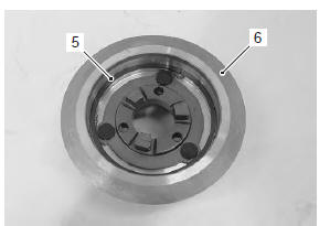
- Install the seat washer (5) to the clutch sleeve hub (6).
- Install the wave spring washers (7) and clutch lifter driven cam (8).
- Apply engine oil to the contacting surfaces of the clutch sleeve hub, clutch lifter drive cam and clutch lifter driven cam.
- Install the clutch lifter drive cam (9).
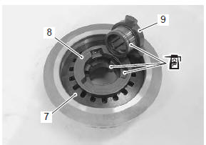
- Install the clutch sleeve hub, washer (10) and spring washer (11).
Note the conical curve side of spring washer (11) faces outside.


- Hold the clutch sleeve hub with the special tool.
 (a): 09920–53740 (clutch sleeve hub
holder)
- Tighten the clutch sleeve hub nut to the specified torque.
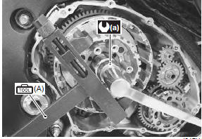
- Lock the clutch sleeve hub nut with a center punch.

- Install the clutch push rod (12) into the countershaft.

- Install the clutch push piece (13), bearing (14) and thrust washer (15) to the countershaft.
Note thrust washer (15) is located between the pressure plate and bearing (14).
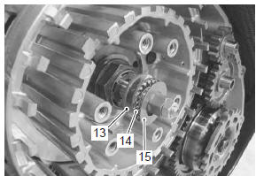
- Install the spring washer seat (16) and spring washer (17) onto the clutch sleeve hub correctly.

- Apply engine oil to the clutch drive plates.
- Insert the clutch drive plates and driven plate one by one into the clutch sleeve hub in the prescribed order.
insert the outermost no. 1 Drive plate claws “a” to the other slits “b” of clutch housing as shown in the figure.
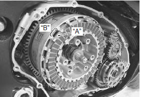

- No. 2 Drive plate (1 pc.)
- No. 1 Drive plate (8 pcs.)
- No. 2 Driven plate (1 pc.)
- No. 1 Driven plate (5 – 7 pcs.)
- No. 3 Driven plate (0 – 2 pcs.)
- Direction of outside
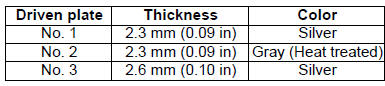
two kinds of drive plate (no. 1 And no. 2) Are equipped in the clutch system, they can be distinguished by inside diameter.

Note three kinds of the driven plate (no. 1, No. 2 And no. 3) Are equipped in the clutch system, they can be distinguished by color and thickness.
The no. 1, No. 2 And no. 3 Driven plates are 8 pcs. In total.
5 – 7 Pcs. Of no. 1 Driven plates are used with 1 pc. Of no. 2 And 0 – 2 pc(-s). Of no. 3 Driven plate(-s) as a set. The no. 3 Driven plate(-s) should be installed in pressure plate side.
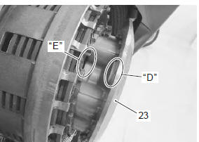
- Install the pressure plate (23).
when install the pressure plate, fit the convex part “d” of the pressure plate onto the concave part “e” of the clutch sleeve hub.
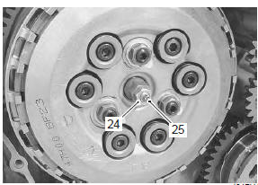
- Install the clutch springs and set bolts.
- Tighten the clutch spring set bolts to the specified torque.
Note tighten the clutch spring set bolt little by little and diagonally.

- Loosen the lock-nut (24) and turn in the clutch release adjusting screw (25) until resistance is felt.
- From that position, turn out the clutch release adjusting screw (25) 1 turn and tighten the lock-nut (24) while holding the screw (25).
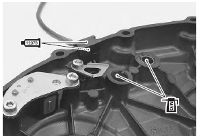
- Apply bond lightly to the mating surfaces at the parting line between the upper and lower crankcases as shown in the figure.
 : Sealant 99000–31140 (suzuki
bond no.1207B or equivalent)
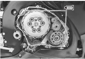
- Install the dowel pins and new gasket (26).
Caution use new gasket to prevent oil leakage.

- Apply bond lightly to the ckp sensor grommet.
 : Sealant 99000–31140 (suzuki
bond no.1207B or equivalent)
- Apply molybdenum oil solution to the starter torque limiter/idle gear no. 2 Shaft holes.
- Install the clutch cover and tighten the clutch cover bolts.
Note fit new gasket washer to the bolt “f” and clamp to the bolt “g”.
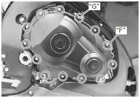
- Route the ckp sensor lead wire properly. Refer to “wiring harness routing diagram” in section 9a .
- ) Install the fuel tank. Refer to “fuel tank removal and installation” in section 1g .
- Pour engine oil. Refer to “engine oil and filter replacement” in section 0b .
Test yourself
A quick Suzuki GSX-R 1000 quiz: every answer comes with an explanation and a link to the manual page.
Was this page helpful?