Electric Parking Brake ECU Communication Stop Mode. Fail-safe Chart. Front Camera Module Communication Stop Mode
Electric Parking Brake ECU Communication Stop Mode
DESCRIPTION
Detection Item | Symptom | Trouble Area |
|---|---|---|
Electric Parking Brake ECU Communication Stop Mode |
Any of the following conditions are met:
|
|
WIRING DIAGRAM
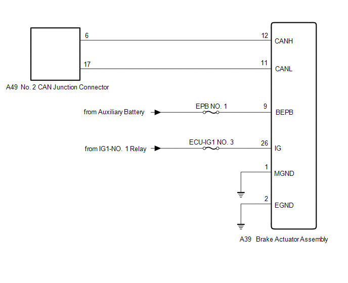
CAUTION:
When performing the confirmation driving pattern, obey all speed limits and traffic laws.
NOTICE:
- Because the order of diagnosis is important to allow correct diagnosis, make sure to begin troubleshooting using How to Proceed with Troubleshooting when CAN communication system related DTCs are output.
Click here

- Before measuring the resistance of the CAN bus, turn the power switch off and leave the vehicle for 1 minute or more without operating the key or any switches, or opening or closing the doors. After that, disconnect the cable from the negative (-) auxiliary battery terminal and leave the vehicle for 1 minute or more before measuring the resistance.
- After turning the power switch off, waiting time may be required before disconnecting the cable from the negative (-) auxiliary battery terminal. Therefore, make sure to read the disconnecting the cable from the negative (-) auxiliary battery terminal notices before proceeding with work.
Click here
- After performing repairs, perform the DTC check procedure and confirm that the DTCs are not output again.
DTC check procedure: Turn the power switch on (IG) and wait for 1 minute or more. Then operate the suspected malfunctioning system and drive the vehicle at 60 km/h or more for 5 minutes or more.
- After the repair, perform the CAN bus check and check that all the ECUs and sensors connected to the CAN communication system are displayed as normal.
Click here
- Inspect the fuses for circuits related to this system before performing the following procedure.
HINT:
- Before disconnecting related connectors for inspection, push in on each connector body to check that the connector is not loose or disconnected.
- When a connector is disconnected, check that the terminals and connector body are not cracked, deformed or corroded.
PROCEDURE
CHECK FOR OPEN IN CAN BUS LINES (BRAKE ACTUATOR ASSEMBLY BRANCH LINE)
(a) Disconnect the cable from the negative (-) auxiliary battery terminal.
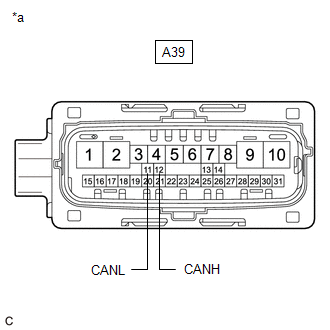
(b) Disconnect the A39 brake actuator assembly connector.
(c) Measure the resistance according to the value(s) in the table below. Standard Resistance:
|
|
| NG |  |
REPAIR OR REPLACE CAN BRANCH LINES OR CONNECTOR (BRAKE ACTUATOR ASSEMBLY) |
|

CHECK HARNESS AND CONNECTOR (POWER SOURCE CIRCUIT)
(a) Measure the resistance according to the value(s) in the table below. Standard Resistance:
|
|
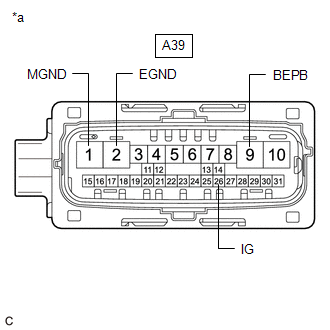
(b) Reconnect the cable to the negative (-) auxiliary battery terminal.
(c) Measure the voltage according to the value(s) in the table below.
Standard Voltage:
Tester Connection | Condition | Specified Condition |
|---|---|---|
A39-9 (BEPB) - Body ground |
Power switch off |
11 to 14 V |
A39-26 (IG) - Body ground |
Power switch on (IG) |
11 to 14 V |
| OK | |
REPLACE BRAKE ACTUATOR ASSEMBLY |
| NG | |
REPAIR OR REPLACE HARNESS OR CONNECTOR (POWER SOURCE CIRCUIT) |
Fail-safe Chart
FAIL-SAFE CHART
FAIL-SAFE FUNCTION
(a) When communication fails in any of the CAN bus lines (communication lines), a fail-safe function(s) will operate. The fail-safe function that is specified for each system operates to prevent those systems from malfunctioning.
(b) The following table shows the effects on each system when communication is impossible. (For further details, see the pages for each system.)
Function | Control Master (Main ECU to determine controls) | System Related | Fail-safe Operation | Driver Detectable | DTC Detection (ECU that stored DTC) |
|---|---|---|---|---|---|
Regenerative Operation
|
Hybrid vehicle control ECU |
Brake booster with master cylinder assembly |
Normal driving |
|
U117087 (Hybrid vehicle control ECU) |
Drive Torque Control
|
Hybrid vehicle control ECU |
ECM |
Normal driving |
|
U010087 (Hybrid vehicle control ECU) |
Drive Torque Control
|
Hybrid vehicle control ECU |
Inverter with converter assembly |
Normal driving |
Master warning light illuminates. |
U011087 (Hybrid vehicle control ECU) |
Drive Torque Control
|
Hybrid vehicle control ECU |
Brake booster with master cylinder assembly |
Normal driving |
MIL illuminates. |
U012987 (Hybrid vehicle control ECU) |
Air Conditioning Control
|
Hybrid vehicle control ECU |
Air conditioning amplifier assembly |
- |
- |
U016487 (Hybrid vehicle control ECU) |
High voltage shut off control when the vehicle is damaged.
|
Hybrid vehicle control ECU |
Airbag ECU assembly |
Normal driving |
Master warning light illuminates. |
U015187 (Hybrid vehicle control ECU) |
Motor/Generator Control
|
|
|
When the brake booster with master cylinder assembly is not communicating:
When an ECU other than the brake booster with master cylinder assembly is not communicating:
|
|
U010087 U029387 U117087 (Inverter with converter assembly) |
Anti-lock Brake System Control
|
Brake booster with master cylinder assembly |
Airbag ECU assembly |
Control is permitted. |
|
U0073 U0124 (Brake booster with master cylinder assembly) |
Vehicle Stability Control / Traction Control
|
Brake booster with master cylinder assembly |
|
Control is permitted. |
|
U0073 U0110 U0124 U0126 U0293 (Brake booster with master cylinder assembly) |
Hybrid Vehicle Regenerative Brake Coordinate Control
|
Brake booster with master cylinder assembly |
|
When the airbag ECU assembly is not communicating:
When an ECU other than the airbag ECU assembly is not communicating:
|
|
U0073 U0110 U0120 U0124 U0293 (Brake booster with master cylinder assembly) |
Hill-start Assist Control
|
Brake booster with master cylinder assembly |
|
|
|
U0073 U0110 U0124 U0126 U0293 (Brake booster with master cylinder assembly) |
Brake Hold Control
|
Brake booster with master cylinder assembly |
|
When the airbag ECU assembly is not communicating:
When an ECU other than the airbag ECU assembly is not communicating:
|
|
U0073 U0124 U0128 U0293 (Brake booster with master cylinder assembly) |
Dynamic Parking Brake
|
Brake actuator assembly |
Brake booster with master cylinder assembly |
The vehicle cannot be determined as stopped. |
Brake warning light / yellow (minor malfunction) illuminates. |
U0073 U0129 (Brake actuator assembly) |
Static Parking Brake
|
Brake actuator assembly |
Brake booster with master cylinder assembly |
The vehicle cannot be determined as stopped. |
Brake warning light / yellow (minor malfunction) illuminates. |
U0073 U0129 (Brake actuator assembly) |
Shift-linked Function
|
Brake actuator assembly |
|
Shift-linked function is prohibited. |
Brake warning light / yellow (minor malfunction) illuminates. |
U0073 U0124 U0129 U0293 (Brake actuator assembly) |
Brake Hold Function
|
Brake actuator assembly |
Brake booster with master cylinder assembly |
Brake hold function prohibited. |
Brake warning light / yellow (minor malfunction) illuminates. |
U0073 U0129 (Brake actuator assembly) |
Occupant Classification System
|
Airbag ECU assembly |
Occupant detection ECU |
SRS components do not deploy. |
SRS warning light illuminates. |
U0154 (Airbag ECU assembly) |
Occupant Detection |
Occupant detection ECU |
|
Sends signals indicating a malfunction to the airbag ECU assembly. |
SRS warning light illuminates. |
U0125 U0129 (Occupant detection ECU) |
Vehicle Speed Display |
Combination meter assembly |
Brake booster with master cylinder assembly |
Speedometer is controlled based on a default vehicle speed of 0 km/h. |
|
U012987 (Combination meter assembly) |
Meter Display
|
Combination meter assembly |
|
Vehicle information is not displayed. |
Abnormal light operation |
U010087 U012987 U013187 U014287 U015187 U016387 U016487 U018287 U023387 U023A87 U029387 U032787 U110687 U111087 U111287 U113387 (Combination meter assembly) |
Speedometer
|
Meter mirror sub-assembly |
Combination meter assembly |
|
- |
U015587 (Meter mirror sub-assembly) |
Display Brightness Adjustment
|
Meter mirror sub-assembly |
Combination meter assembly |
The last valid state is maintained. |
- |
U015587 (Meter mirror sub-assembly) |
Display Position Adjustment
|
Meter mirror sub-assembly |
Combination meter assembly |
The last valid state is maintained. |
- |
U015587 (Meter mirror sub-assembly) |
Display Rotation Adjustment
|
Meter mirror sub-assembly |
Combination meter assembly |
The last valid state is maintained. |
- |
U015587 (Meter mirror sub-assembly) |
Hybrid System Indicator |
Meter mirror sub-assembly |
Hybrid vehicle control ECU |
Operates under default control. |
- |
U029387 (Meter mirror sub-assembly) |
Shift Position Display
|
Meter mirror sub-assembly |
Hybrid vehicle control ECU |
Not displayed. |
- |
U029387 (Meter mirror sub-assembly) |
Pre-collision System
|
Meter mirror sub-assembly |
Driving support ECU assembly |
Not displayed. |
- |
U110487 (Meter mirror sub-assembly) |
Dynamic Radar Cruise Control System
|
Meter mirror sub-assembly |
Hybrid vehicle control ECU |
Not displayed. |
- |
U029387 (Meter mirror sub-assembly) |
Lane Departure Alert System
|
Meter mirror sub-assembly |
Forward recognition camera |
Not displayed. |
- |
U023A87 (Meter mirror sub-assembly) |
Intelligent Clearance Sonar System
|
Meter mirror sub-assembly |
Clearance warning ECU assembly |
Not displayed. |
- |
U111087 (Meter mirror sub-assembly) |
Information
|
Meter mirror sub-assembly |
Combination meter assembly |
Not displayed. |
- |
U015587 (Meter mirror sub-assembly) |
Air Conditioning Control
|
Air conditioning amplifier assembly |
|
Control is performed based on default coolant temperature of 80 °C. |
- |
U0293 (Air conditioning amplifier assembly) |
Panel Dimming Control
|
Air conditioning amplifier assembly |
Main body ECU (multiplex network body ECU) |
While the power switch is on (IG), previous values are maintained (during a reset, dimming control is performed). |
- |
U0142 (Air conditioning amplifier assembly) |
Ambient Temperature Correction Control
|
Air conditioning amplifier assembly |
Combination meter assembly |
Control is performed based on default vehicle speed of 0 km/h. |
- |
U0155 (Air conditioning amplifier assembly) |
Entry Function
|
|
|
Attempts another unlock operation. |
|
U0100 U0142 U0155 (Certification ECU (smart key ECU assembly)) |
Wireless Function
|
Main body ECU (multiplex network body ECU) |
Certification ECU (smart key ECU assembly) |
- |
Wireless lock/unlock functions and luggage compartment opener can be operated when the power switch is on (IG). |
U0142 (Certification ECU (smart key ECU assembly)) |
Power Switch Backlighting Control
|
Certification ECU (smart key ECU assembly) |
|
|
- |
U0142 (Certification ECU (smart key ECU assembly)) |
Security Indicator Display Function
|
Certification ECU (smart key ECU assembly) |
Main body ECU (multiplex network body ECU) |
- |
Security condition cannot display normally (illuminates during security warning preparation/security warning). |
U0142 (Certification ECU (smart key ECU assembly)) |
Security Indicator Display Function
|
Certification ECU (smart key ECU assembly) |
Hybrid vehicle control ECU |
- |
Entry and start warning cannot display normally.
|
U0293 (Certification ECU (smart key ECU assembly)) |
Power Switch (Power Source Control)
|
Certification ECU (smart key ECU assembly) |
|
- |
|
U0140 U0155 U0293 (Certification ECU (smart key ECU assembly)) |
Cooperative Operation
|
ECM |
Swing grille actuator assembly |
The grille shutter is kept fully open. |
- |
U028487 (ECM) |
Cooperative Operation
|
ECM |
Inverter with converter assembly |
Engine is stopped. |
MIL illuminates. |
U011087 (ECM) |
Cooperative Operation
|
ECM |
Hybrid vehicle control ECU |
Engine is stopped. |
MIL illuminates. |
U029387 (ECM) |
Blind Spot Monitor Control
|
Blind spot monitor sensor RH |
|
- |
|
U0125 U0126 U0129 U0142 U0293 (Blind spot monitor sensor RH) |
Grille Shutter Opening or Closing Operation Control
|
Swing grille actuator assembly |
|
Grille shutter opening operation is performed. |
- |
- |
Automatic High Beam System
|
Forward recognition camera |
|
Performs control based on the signals received before the malfunction occurred. |
Displays messages on the multi-information display. |
- |
LDA/SWS System (Recognizes the lane markers of the lane the vehicle is in using the forward recognition camera and performs the following operations based on the vehicle condition and information captured by the forward recognition camera.)
|
Forward recognition camera |
|
Control stops. |
|
U0101 U0123 U0126 U0129 U0131 U0142 U0155 U0235 U0293 U1104 (Forward recognition camera) |
Pre-collision System
|
Forward recognition camera |
|
Detection processing is reset and signals indicating that the forward recognition camera is not detecting objects are sent to the driving support ECU assembly. |
|
U0123 U0129 U0142 U0235 U0293 U1104 (Forward recognition camera) |
Pre-collision System
|
Driving support ECU assembly |
|
Control stops. |
|
U0125 U0126 U0129 U0155 U0235 U023A U0293 U1002 U1104 (Driving support ECU assembly) |
Dynamic Radar Cruise Control System
|
Hybrid vehicle control ECU |
|
Control stops. |
Displays messages on the multi-information display. |
U012287 U029387 U110487 (Hybrid vehicle control ECU) |
Dynamic Radar Cruise Control System
|
Driving support ECU assembly |
|
Control stops. |
Displays messages on the multi-information display. |
U0125 U0126 U0129 U0235 U0293 U1104 (Driving support ECU assembly) |
Power Steering Control
|
Rack and pinion power steering gear assembly |
|
|
EPS warning light illuminates. |
U0129 U0293 (Rack and pinion power steering gear assembly) |
Assist Map Selection
|
Rack and pinion power steering gear assembly |
|
Default map is used to assist because proper assist map cannot be selected. (Steering feel may be different.) |
EPS warning light illuminates. |
C1581 (Rack and pinion power steering gear assembly) |
Auto Location
|
Tire pressure warning ECU and receiver |
Brake booster with master cylinder assembly |
Auto Location function is prohibited. |
- |
U0129 (Tire pressure warning ECU and receiver) |
Door Lock
|
Main body ECU (multiplex network body ECU) |
Airbag ECU assembly |
Key linked door lock/unlock function is performed even when the power switch is on (IG) and the driver seatbelt is fastened. |
- |
U0151 (Main body ECU (multiplex network body ECU)) |
Shift-linked Automatic Door Lock Function
|
Main body ECU (multiplex network body ECU) |
Hybrid vehicle control ECU |
All of the doors are not locked automatically when all of the following conditions are met.
|
- |
U0101 (Main body ECU (multiplex network body ECU)) |
Shift-linked Automatic Door Unlock Function
|
Main body ECU (multiplex network body ECU) |
|
All of the doors are not locked automatically when all of the following conditions are met.
|
- |
U0101 U0155 (Main body ECU (multiplex network body ECU)) |
Speed-sensitive Automatic Door Lock Function
|
Main body ECU (multiplex network body ECU) |
Combination meter assembly |
All of the doors are not locked automatically when all of the following conditions are met.
|
- |
U0155 (Main body ECU (multiplex network body ECU)) |
Manual Unlock Prohibition Function
|
Main body ECU (multiplex network body ECU) |
|
|
- |
U0100 U0293 (Main body ECU (multiplex network body ECU)) |
Power Door Lock Control System Customize Setting
|
Main body ECU (multiplex network body ECU) |
Hybrid vehicle control ECU |
|
- |
U0101 (Main body ECU (multiplex network body ECU)) |
Wireless Function
|
Main body ECU (multiplex network body ECU) |
Certification ECU (smart key ECU assembly) |
The doors cannot be locked or unlocked via remote operation. |
- |
- |
Entry Lock/Unlock
|
Main body ECU (multiplex network body ECU) |
Certification ECU (smart key ECU assembly) |
The doors cannot be locked or unlocked via remote operation. |
- |
U0327 (Main body ECU (multiplex network body ECU)) |
Wireless Door Lock Buzzer
|
Main body ECU (multiplex network body ECU) |
Certification ECU (smart key ECU assembly) |
The wireless door lock buzzer does not sound when the doors are locked/unlocked by wireless operation. |
- |
U0327 (Main body ECU (multiplex network body ECU)) |
Seat and Mirror Control |
Main body ECU (multiplex network body ECU) |
|
Memory function does not operate. |
- |
U0155 U0199 U0200 U0208 U0327 U1106 U1115 (Main body ECU (multiplex network body ECU)) |
Luggage Compartment Door Opener System
|
Main body ECU (multiplex network body ECU) |
Certification ECU (smart key ECU assembly) |
When the luggage electrical key switch is pushed and held with the luggage compartment door locked, the luggage compartment door does not unlatch. |
- |
U0327 (Main body ECU (multiplex network body ECU)) |
Luggage Compartment Door Opener System
|
Main body ECU (multiplex network body ECU) |
|
When the luggage door opening switch assembly is pushed and held, the luggage compartment door does not unlatch. |
- |
U0101 U0155 (Main body ECU (multiplex network body ECU)) |
Dome Lights
|
Main body ECU (multiplex network body ECU) |
Certification ECU (smart key ECU assembly) |
The interior lights remain off when the electrical key transmitter sub-assembly is close to any of the doors. |
- |
U0327 (Main body ECU (multiplex network body ECU)) |
Dimmer Controlled Illumination
|
Main body ECU (multiplex network body ECU) |
Hybrid vehicle control ECU |
The interior lights remain on without being dimmed when the shift state is park (P) and a shift state other than park (P) is selected. |
- |
U0101 (Main body ECU (multiplex network body ECU)) |
Alarm Function
|
Main body ECU (multiplex network body ECU) |
|
|
- |
U0100 U0120 (Main body ECU (multiplex network body ECU)) |
Auxiliary Battery Saving Function
|
Main body ECU (multiplex network body ECU) |
Certification ECU (smart key ECU assembly) |
When the auxiliary battery is in battery saving mode and any of the doors are approached while holding an entry key, the auxiliary battery saving function is not canceled and the interior illuminations do not illuminate. |
- |
U0327 (Main body ECU (multiplex network body ECU)) |
Headlight System Malfunction Warning Display
|
Main body ECU (multiplex network body ECU) |
|
|
- |
U0100 U0293 (Main body ECU (multiplex network body ECU)) |
Meter Illumination Auto Dimmer
|
Main body ECU (multiplex network body ECU) |
Combination meter assembly |
The meter illumination is dimmed when the tail cancel switch is on. |
- |
U0155 (Main body ECU (multiplex network body ECU)) |
Key Off Operation
|
Main body ECU (multiplex network body ECU) |
|
|
- |
U0100 U0293 (Main body ECU (multiplex network body ECU)) |
Headlights Left Off Warning
|
Main body ECU (multiplex network body ECU) |
Combination meter assembly |
The suggestion that the driver turns the headlights on is not displayed on the multi-information display in the combination meter assembly when the headlight dimmer switch is OFF or TAIL while driving at night. |
- |
U0155 (Main body ECU (multiplex network body ECU)) |
Automatic High Beam System
|
Main body ECU (multiplex network body ECU) |
|
Automatic high beam system does not operate. |
Automatic high beam indicator light flashes. |
U0182 U023A (Main body ECU (multiplex network body ECU)) |
Air Conditioning Control
|
Radio and display receiver assembly |
Air conditioning amplifier assembly |
|
- |
U0073 U0164 (Radio and display receiver assembly) |
Intuitive Parking Assist System Setting/Notification
|
Radio and display receiver assembly |
|
Returns to the previous display. |
- |
U0073 U1110 (Radio and display receiver assembly) |
Fuel Consumption Display
|
Radio and display receiver assembly |
|
|
- |
U0073 U0100 U0129 U0155 U0293 (Radio and display receiver assembly) |
HV Energy Flow Display
|
Radio and display receiver assembly |
Hybrid vehicle control ECU |
|
- |
U0073 U0293 (Radio and display receiver assembly) |
Destination Identification
|
Radio and display receiver assembly |
Main body ECU (multiplex network body ECU) |
Determines the destination according to the last received value and operates accordingly (if there is no last received value, the system operates using the default value). |
Time zone and language selection screen are different from actual destination. |
U0073 U0140 (Radio and display receiver assembly) |
Vehicle Customize Function
|
Radio and display receiver assembly |
|
|
- |
U0073 (Radio and display receiver assembly) |
Back Guide Monitor Function
|
Radio and display receiver assembly |
|
|
- |
U0073 U0265 (Radio and display receiver assembly) |
Remote Service Function
|
Radio and display receiver assembly |
DCM (telematics transceiver) |
The remote screen is not displayed. |
- |
U0073 U0198 (Radio and display receiver assembly) |
Meter-linked Function
|
Radio and display receiver assembly |
Combination meter assembly |
|
- |
U0073 U0155 (Radio and display receiver assembly) |
Information Sound Adjustment Function
|
Radio and display receiver assembly |
Driving support ECU assembly |
Audio mute is canceled. |
- |
U0073 (Radio and display receiver assembly) |
Panoramic View Monitor |
Radio and display receiver assembly |
|
|
- |
U0073 U023B (Radio and display receiver assembly) |
Back Guide Monitor Function
|
Television camera assembly |
|
|
"!" is displayed on the camera screen. |
U0100 U0126 U0140 U0163 U0233 U1000 (Television camera assembly) |
Rear Camera Detection Function
|
Television camera assembly |
|
Control stops. |
Displays messages on the multi-information display. |
U0100 U0126 U0129 U0140 U0163 U0233 U023B U1000 (Television camera assembly) |
Panoramic View Monitor
|
Parking assist ECU |
|
|
"!" is displayed on the camera screen. |
U0073 U0100 U0126 U0129 U0140 U0163 U0233 U0265 U1110 U1000 (Parking assist ECU) |
Ambient Temperature Display
|
Clearance warning ECU assembly |
Air conditioning amplifier assembly |
- |
- |
U0164 (Clearance warning ECU assembly) |
Intuitive Parking Assist System
|
Clearance warning ECU assembly |
|
Intuitive parking assist control is stopped. |
- |
U0073 U0100 U0126 U0129 U0293 U1000 (Clearance warning ECU assembly) |
Intelligent Clearance Sonar System
|
Clearance warning ECU assembly |
|
Intelligent clearance sonar control is stopped. |
|
U0073 U0100 U0124 U0126 U0129 U0232 U0233 U0293 U1000 (Clearance warning ECU assembly) |
Remote Check
|
DCM (telematics transceiver) |
Combination meter assembly |
Function is disabled. |
Notification displayed on smartphone via the application. |
U0155 (DCM (telematics transceiver)) |
TOYOTA Entune System
|
DCM (telematics transceiver) |
|
Function is disabled. |
Notification displayed on smartphone via the application. |
U0142 U0155 (DCM (telematics transceiver)) |
TOYOTA Entune System
|
DCM (telematics transceiver) |
Main body ECU (multiplex network body ECU) |
Function is disabled. |
Notification displayed on smartphone via the application. |
U0142 (DCM (telematics transceiver)) |
TOYOTA Entune System
|
DCM (telematics transceiver) |
Main body ECU (multiplex network body ECU) |
Function is disabled. |
Notification displayed on smartphone via the application. |
U0142 (DCM (telematics transceiver)) |
TOYOTA Entune System
|
DCM (telematics transceiver) |
Main body ECU (multiplex network body ECU) |
Function is disabled. |
Notification displayed on smartphone via the application. |
U0142 (DCM (telematics transceiver)) |
Mirror Operation Control
|
|
Main body ECU (multiplex network body ECU) |
Manual mirror operation is prohibited. |
- |
U0142 (Outer mirror control ECU assembly LH) U0142 (Outer mirror control ECU assembly RH) |
Reverse-shift Linked Door Mirror Operation
|
|
Main body ECU (multiplex network body ECU) |
Reverse-shift linked door mirror function does not operate. |
- |
- |
Mirror Surface Position Memory and Recall
|
|
Main body ECU (multiplex network body ECU) |
Mirror surface position cannot be memorized or recalled. |
- |
- |
Mirror Heater Control
|
|
|
Mirror heaters do not operate. |
- |
U0142 (Outer mirror control ECU assembly LH) U0142 (Outer mirror control ECU assembly RH) |
Mirror Retract/Return Operation
|
|
Main body ECU (multiplex network body ECU) |
Mirrors cannot be retracted or returned. |
- |
- |
Illumination Control
|
|
Main body ECU (multiplex network body ECU) |
Mirror foot light does not illuminate. |
- |
- |
Auto Away Function
|
Multiplex tilt and telescopic ECU |
|
Control is suspended (manual operation is still possible). |
- |
U014287 U015587 (Multiplex tilt and telescopic ECU) |
Auto Return Function
|
Multiplex tilt and telescopic ECU |
|
Control is suspended (manual operation is still possible). |
- |
U014287 U015587 (Multiplex tilt and telescopic ECU) |
Memory Function
|
Multiplex tilt and telescopic ECU |
|
Control is suspended (manual operation is still possible). |
- |
U014287 U015587 U020887 (Multiplex tilt and telescopic ECU) |
User Customize Function
|
Multiplex tilt and telescopic ECU |
|
Control is suspended (manual operation is still possible). |
- |
U014287 (Multiplex tilt and telescopic ECU) |
Memory Seat Playback Control
|
Position control ECU assembly LH |
Main body ECU (multiplex network body ECU) |
Control stops. |
- |
- |
|
Position control ECU assembly LH |
Main body ECU (multiplex network body ECU) |
Control stops. |
- |
- |
Light control
|
|
Main body ECU (multiplex network body ECU) |
|
- |
U0142 (Headlight ECU sub-assembly LH) U0142 (Headlight ECU sub-assembly RH) |
Front Camera Module Communication Stop Mode
DESCRIPTION
Detection Item | Symptom | Trouble Area |
|---|---|---|
Front Camera Module Communication Stop Mode |
Any of the following conditions are met:
|
|
WIRING DIAGRAM
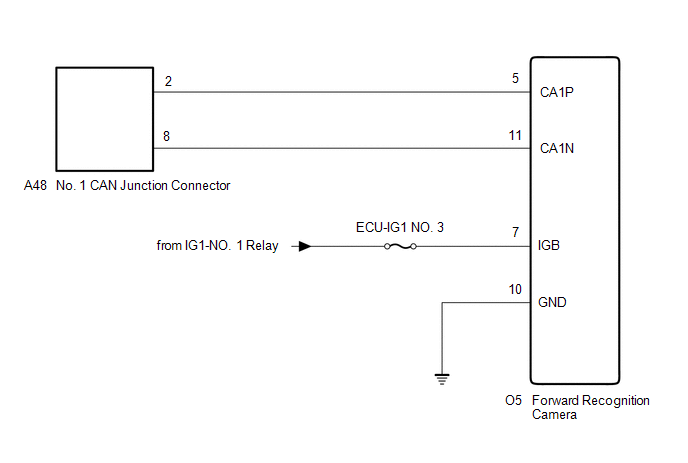
CAUTION:
When performing the confirmation driving pattern, obey all speed limits and traffic laws.
NOTICE:
- Because the order of diagnosis is important to allow correct diagnosis, make sure to begin troubleshooting using How to Proceed with Troubleshooting when CAN communication system related DTCs are output.
Click here

- Before measuring the resistance of the CAN bus, turn the power switch off and leave the vehicle for 1 minute or more without operating the key or any switches, or opening or closing the doors. After that, disconnect the cable from the negative (-) auxiliary battery terminal and leave the vehicle for 1 minute or more before measuring the resistance.
- After turning the power switch off, waiting time may be required before disconnecting the cable from the negative (-) auxiliary battery terminal. Therefore, make sure to read the disconnecting the cable from the negative (-) auxiliary battery terminal notices before proceeding with work.
Click here
- After performing repairs, perform the DTC check procedure and confirm that the DTCs are not output again.
DTC check procedure: Turn the power switch on (IG) and wait for 1 minute or more. Then operate the suspected malfunctioning system and drive the vehicle at 60 km/h or more for 5 minutes or more.
- After the repair, perform the CAN bus check and check that all the ECUs and sensors connected to the CAN communication system are displayed as normal.
Click here
- Inspect the fuses for circuits related to this system before performing the following procedure.
HINT:
- Before disconnecting related connectors for inspection, push in on each connector body to check that the connector is not loose or disconnected.
- When a connector is disconnected, check that the terminals and connector body are not cracked, deformed or corroded.
PROCEDURE
CHECK FOR OPEN IN CAN BUS LINES (FORWARD RECOGNITION CAMERA BRANCH LINE)
(a) Disconnect the cable from the negative (-) auxiliary battery terminal.
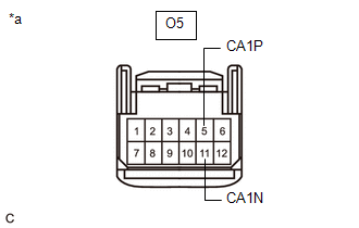
(b) Disconnect the O5 forward recognition camera connector.
(c) Measure the resistance according to the value(s) in the table below. Standard Resistance:
|
|
| NG |  |
REPAIR OR REPLACE CAN BRANCH LINES OR CONNECTOR (FORWARD RECOGNITION CAMERA) |
|

CHECK HARNESS AND CONNECTOR (POWER SOURCE CIRCUIT)
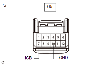
(a) Measure the resistance according to the value(s) in the table below. Standard Resistance:
|
|
(b) Reconnect the cable to the negative (-) auxiliary battery terminal.
(c) Measure the voltage according to the value(s) in the table below.
Standard Voltage:
Tester Connection | Condition | Specified Condition |
|---|---|---|
O5-7 (IGB) - Body ground |
Power switch on (IG) |
11 to 14 V |
| OK | |
REPLACE FORWARD RECOGNITION CAMERA |
| NG | |
REPAIR OR REPLACE HARNESS OR CONNECTOR (POWER SOURCE CIRCUIT) |