Power Steering ECU Communication Stop Mode. Precaution. Problem Symptoms Table
Power Steering ECU Communication Stop Mode
DESCRIPTION
Detection Item | Symptom | Trouble Area |
|---|---|---|
Power Steering ECU Communication Stop Mode |
Any of the following conditions are met:
|
|
WIRING DIAGRAM
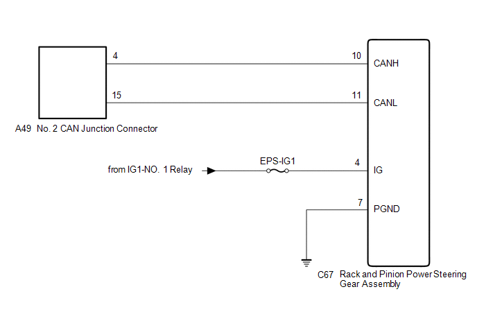
CAUTION:
When performing the confirmation driving pattern, obey all speed limits and traffic laws.
NOTICE:
- Because the order of diagnosis is important to allow correct diagnosis, make sure to begin troubleshooting using How to Proceed with Troubleshooting when CAN communication system related DTCs are output.
Click here

- Before measuring the resistance of the CAN bus, turn the power switch off and leave the vehicle for 1 minute or more without operating the key or any switches, or opening or closing the doors. After that, disconnect the cable from the negative (-) auxiliary battery terminal and leave the vehicle for 1 minute or more before measuring the resistance.
- After turning the power switch off, waiting time may be required before disconnecting the cable from the negative (-) auxiliary battery terminal. Therefore, make sure to read the disconnecting the cable from the negative (-) auxiliary battery terminal notices before proceeding with work.
Click here
- After performing repairs, perform the DTC check procedure and confirm that the DTCs are not output again.
DTC check procedure: Turn the power switch on (IG) and wait for 1 minute or more. Then operate the suspected malfunctioning system and drive the vehicle at 60 km/h or more for 5 minutes or more.
- After the repair, perform the CAN bus check and check that all the ECUs and sensors connected to the CAN communication system are displayed as normal.
Click here
- Inspect the fuses for circuits related to this system before performing the following procedure.
HINT:
- Before disconnecting related connectors for inspection, push in on each connector body to check that the connector is not loose or disconnected.
- When a connector is disconnected, check that the terminals and connector body are not cracked, deformed or corroded.
PROCEDURE
CHECK FOR OPEN IN CAN BUS LINES (RACK AND PINION POWER STEERING GEAR ASSEMBLY BRANCH LINE)
(a) Disconnect the cable from the negative (-) auxiliary battery terminal.
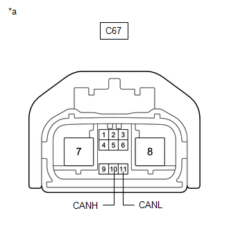
(b) Disconnect the C67 rack and pinion power steering gear assembly connector.
(c) Measure the resistance according to the value(s) in the table below. Standard Resistance:
|
|
| NG |  |
REPAIR OR REPLACE CAN BRANCH LINES OR CONNECTOR (RACK AND PINION POWER STEERING GEAR ASSEMBLY) |
|

CHECK HARNESS AND CONNECTOR (POWER SOURCE CIRCUIT)
(a) Measure the resistance according to the value(s) in the table below. Standard Resistance:
|
|
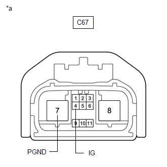
(b) Reconnect the cable to the negative (-) auxiliary battery terminal.
(c) Measure the voltage according to the value(s) in the table below.
Standard Voltage:
Tester Connection | Condition | Specified Condition |
|---|---|---|
C67-4 (IG) - Body ground |
Power switch on (IG) |
11 to 14 V |
| OK | |
REPLACE RACK AND PINION POWER STEERING GEAR ASSEMBLY |
| NG | |
REPAIR OR REPLACE HARNESS OR CONNECTOR (POWER SOURCE CIRCUIT) |
Precaution
PRECAUTION
NOTICE FOR INITIALIZATION
NOTICE:
When disconnecting the cable from the negative (-) auxiliary battery terminal, initialize the following systems after the cable is reconnected.
System | See Procedure |
|---|---|
Lane Departure Alert System (w/ Steering Control) |
 |
Pre-collision System |
|
Intelligent Clearance Sonar System* |
|
Lighting System (for HV Model with Cornering Light) |
|
Parking Assist Monitor System |
|
Panoramic View Monitor System |
*: When performing learning using the Techstream.
Click here
CAN COMMUNICATION SYSTEM TROUBLESHOOTING
(a) Because the order of diagnosis is important to allow correct diagnosis, make sure to begin troubleshooting using How to Proceed with Troubleshooting when CAN communication system related DTCs are output.
Click here
(b) Precaution for steering system handling
(1) Be careful when replacing parts. Incorrect replacement could affect the performance of the steering system and result in hazardous driving.
Click here
(c) Precaution for SRS airbag system handling
NOTICE:
This vehicle is equipped with a Supplemental Restraint System (SRS) which includes parts such as airbags for the driver and front passenger. Failure to carry out service operations in the correct sequence could cause unexpected SRS deployment during servicing and may cause a serious accident. Before servicing (including removal or installation of parts, inspection or replacement), be sure to read Precaution for SRS.
Click here
(d) Precaution for when disconnecting a wire harness from a CAN junction connector
(1) When disconnecting a wire harness from a CAN junction connector, use tape or tags to identify each connector and make sure to reconnect each connector to its original location on the CAN junction connector.
HINT:
- Reconnecting a connector to a location other than its original location on the CAN junction connector will not affect system performance. However, reconnecting connectors to their original locations makes future maintenance easier and avoids negative effects on wire harnesses, such as excessive tension.
- For information on how to identify the ECUs or sensors connected to the CAN junction connector, refer to Terminals of ECU.
Click here
(e) Bus line repair
(1) After repairing a bus line with solder, wrap the repaired area with electrical tape.
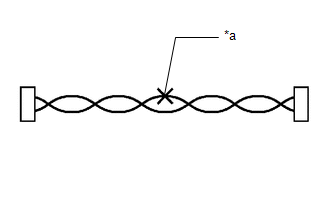
*a |
Soldered Area to Be Wrapped with Electrical Tape |
NOTICE:
- When installing, make sure that these lines are twisted, because CAN bus lines are likely to be influenced by electrical noise if the bus lines are not twisted.
- Ensure that there is no gap between the CANH wire and CANL wire.
- Make sure that the distance between the first twist of the wires and the connector is less than 80 mm (3.15 in).
- When repairing the CAN bus lines, do not change the length of the lines. (Make sure that the length of the CANH bus line and CANL bus line are the same.)
(2) Do not use bypass wiring between connectors.
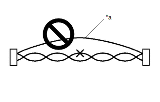
*a |
Bypass Wire |
NOTICE:
- The ability of the twisted bus lines to resist interference will be lost if bypass wiring is used.
- Do not use a twisted pair of wires for bypass wiring.
(f) Connector handling
(1) When checking resistance with a tester, insert the tester probes from the backside (harness side) of the connector.
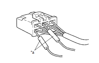
*a |
Tester Probe |
(2) When it is not possible to insert the tester from the backside of the connector, using service wires, measure from the front side of the connector.
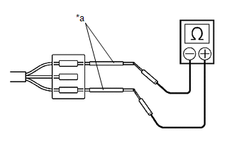
*a |
Service Wire |
(g) Precaution for when replacing a gateway function equipped ECU (sub bus monitoring ECU)
(1) When replacing a gateway equipped function ECU (sub bus monitoring ECU) with one which was installed to another vehicle, perform initialization of the sub bus monitoring ECU in order to clear stored bus information.
Click here
NOTICE:
If the stored bus information does not match the current sub bus configuration, DTCs may be stored and fail-safe functions may operate.
HINT:
It is not necessary to perform initialization of a gateway monitoring ECU (sub bus monitoring ECU) when using a sub bus monitoring ECU which was installed to another vehicle with the same sub bus configuration.
(h) Precautions for when a gateway function equipped ECU (sub bus monitor ECU) detects communication DTCs for ECUs not connected to the ECU
(1) Refer to precautions when replacing a gateway function equipped ECU (sub bus monitoring ECU) and initialize the connection information of the ECU.
(2) Clear the DTCs and check that no DTCs are output.
(i) Difference between genuine navigation receivers/radio and display receivers and optional navigation receivers/radio and display receivers
(1) Some optional navigation receivers/radio and display receivers are available as CAN compatible devices. Be aware that some optional navigation receivers/radio and display receivers do not have the same diagnostic features or characteristics of genuine navigation receivers/radio and display receivers.
NOTICE:
- Optional navigation receivers/radio and display receivers receive data from the CAN communication system. However, most optional navigation receivers/radio and display receivers do not send signals to the CAN bus main line.
- Most optional navigation receivers/radio and display receivers will not be displayed on the "CAN Bus Check" screen of the Techstream.
- When checking for DTCs using the Techstream, DTCs for optional navigation receivers/radio and display receivers will not be displayed on the Techstream.
Problem Symptoms Table
PROBLEM SYMPTOMS TABLE
HINT:
- Use the table below to help determine the cause of problem symptoms.
- Inspect the fuses and relays related to this system before inspecting the suspected areas below.
- Because the order of diagnosis is important to allow correct diagnosis, make sure to begin troubleshooting using How to Proceed with Troubleshooting when CAN communication system related DTCs are output.
Click here

Symptom | Suspected Area | Link |
|---|---|---|
Either of the following:
|
Open in Bus 1 Main Bus Line |
|
Either of the following:
|
Short in Bus 1 Lines |
|
Any of the following:
|
Short to +B in Bus 1 Line |
|
Any of the following:
|
Short to GND in Bus 1 Line |
|
Resistance between CANH and CANL is normal in Bus 1 and the problem symptom pattern in How to Use "Communication Bus Check" Screen in Inspection matches the symptoms when there is an open in one wire of a branch line in Bus 1. |
Open in One Side of Bus 1 Branch Line |
|
Either of the following:
|
Open in Bus 2 Main Bus Line |
|
Either of the following:
|
Short in Bus 2 Lines |
|
Any of the following:
|
Short to +B in Bus 2 Line |
|
Any of the following:
|
Short to GND in Bus 2 Line |
|
Resistance between CANH and CANL is normal in Bus 2 and the problem symptom pattern in How to Use "Communication Bus Check" Screen in Inspection matches the symptoms when there is an open in one wire of a branch line in Bus 2. |
Open in One Side of Bus 2 Branch Line |
|
Either of the following:
|
Open in Bus 3 Main Bus Line |
|
Either of the following:
|
Short in Bus 3 Lines |
|
Any of the following:
|
Short to +B in Bus 3 Line |
|
Any of the following:
|
Short to GND in Bus 3 Line |
|
Resistance between CANH and CANL is normal in Bus 3 and the problem symptom pattern in How to Use "Communication Bus Check" Screen in Inspection matches the symptoms when there is an open in one wire of a branch line in Bus 3. |
Open in One Side of Bus 3 Branch Line |
|
Either of the following:
|
Open in Bus 4 Main Bus Line |
|
Either of the following:
|
Short in Bus 4 Lines |
|
Any of the following:
|
Short to +B in Bus 4 Line |
|
Any of the following:
|
Short to GND in Bus 4 Line |
|
Resistance between CANH and CANL is normal in Bus 4 and the problem symptom pattern in How to Use "Communication Bus Check" Screen in Inspection matches the symptoms when there is an open in one wire of a branch line in Bus 4. |
Open in One Side of Bus 4 Branch Line |
|
Either of the following:
|
Open in Bus 5 Main Bus Line |
|
Either of the following:
|
Short in Bus 5 Lines |
|
Any of the following:
|
Short to +B in Bus 5 Line |
|
Any of the following:
|
Short to GND in Bus 5 Line |
|
Resistance between CANH and CANL is normal in Bus 5 and the problem symptom pattern in How to Use "Communication Bus Check" Screen in Inspection matches the symptoms when there is an open in one wire of a branch line in Bus 5. |
Open in One Side of Bus 5 Branch Line |
|
HINT:
The suspected communication stop area can be determined based on the ECUs or sensors that are displayed as not communicating on the "Communication Bus Check" screen or "Communication Bus Check (Detail)" screen and by referring to the following table.
Communication Stop Mode Table (Open in bus line or other communication stop)Symptom | Suspected Area | Link |
|---|---|---|
Either of the following is met:
|
Hybrid Vehicle Control ECU Communication Stop Mode |
|
Either of the following is met:
|
Skid Control ECU Communication Stop Mode |
|
Either of the following is met:
|
Clearance Warning ECU Communication Stop Mode |
|
Either of the following is met:
|
Air Conditioning Amplifier Communication Stop Mode |
|
Either of the following is met:
|
Power Steering ECU Communication Stop Mode |
|
Either of the following is met:
|
Steering Angle Sensor Communication Stop Mode |
|
Either of the following is met:
|
ECM Communication Stop Mode |
|
Either of the following is met:
|
Main Body ECU Communication Stop Mode |
|
Either of the following is met:
|
Combination Meter ECU Communication Stop Mode |
|
Either of the following is met:
|
Certification ECU Communication Stop Mode |
|
Either of the following is met:
|
Center Airbag Sensor Communication Stop Mode |
|
Either of the following is met:
|
Headlight ECU RH Communication Stop Mode |
|
Either of the following is met:
|
Headlight ECU LH Communication Stop Mode |
|
Either of the following is met:
|
Electric Parking Brake ECU Communication Stop Mode |
|
Either of the following is met:
|
Radio Receiver Assembly Communication Stop Mode |
|
Either of the following is met:
|
Blind Spot Monitor Sensor Communication Stop Mode |
|
Either of the following is met:
|
Parking Assist ECU Communication Stop Mode |
|
Either of the following is met:
|
Tilt and Telescopic ECU Communication Stop Mode |
|
Either of the following is met:
|
DCM Communication Stop Mode |
|
Either of the following is met:
|
Driver Seat Control ECU Communication Stop Mode |
|
Either of the following is met:
|
Door Mirror ECU LH Communication Stop Mode |
|
Either of the following is met:
|
Door Mirror ECU RH Communication Stop Mode |
|
Either of the following is met:
|
Driving Support ECU Communication Stop Mode |
|
Either of the following is met:
|
Headup Display Communication Stop Mode |
|
Either of the following is met:
|
Millimeter Wave Radar Sensor Communication Stop Mode |
|
Either of the following is met:
|
Motor Generator Control ECU Communication Stop Mode |
|
Either of the following is met:
|
Rear Television Camera Communication Stop Mode |
|
Either of the following is met:
|
Restraints Occupant Classification System Module Communication Stop Mode |
|
Either of the following is met:
|
Grille Shutter Communication Stop Mode |
|
Either of the following is met:
|
Front Camera Module Communication Stop Mode |
|
Either of the following is met:
|
Tire Pressure Monitor ECU Communication Stop Mode |
|
Symptom | Suspected Area | Link |
|---|---|---|
Although CAN communication is currently normal, an ECU connected to the CAN communication system has CAN communication DTCs. |
The probable part for which communication is interrupted can be determined using DTC Combination Table and comparing the DTCs output from ECUs connected to the CAN communication system. |
|