Disassembly
DISASSEMBLY
PRECAUTION / NOTICE / HINT
NOTICE:
- Do not drop the power steering ECU assembly, strike it with tools or subject it to impact.
- If the power steering ECU assembly is subjected to impact, replace it with a new one.
- Do not pull on the wire harness.
- Keep moisture away from the power steering ECU assembly.
- Do not loosen bolts that are not specified in the procedure.
- Do not allow foreign matter to contaminate the power steering ECU assembly.
PROCEDURE
1. REMOVE TRANSPONDER KEY COIL (without Smart Key System)
Click here
2. REMOVE STEERING COLUMN UPPER BRACKET SUB-ASSEMBLY WITH SWITCH (without Smart Key System)
(a) Secure the steering column assembly in a vise between aluminum plates.
NOTICE:
Do not overtighten the vise.
(b) Using a center punch, mark the center of the shear bolt.
(c) Using a 3 to 4 mm (0.119 to 0.157 in.) drill, drill a hole in the bolt.
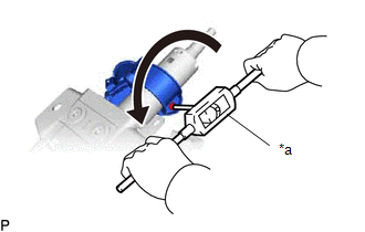
(d) Using a screw extractor, remove the bolt and the steering column upper bracket sub-assembly with switch from the steering column assembly. |
|
3. REMOVE IGNITION LOCK CYLINDER LOCK ASSEMBLY (without Smart Key System)
(a) Turn the ignition switch to the ACC position. |
|
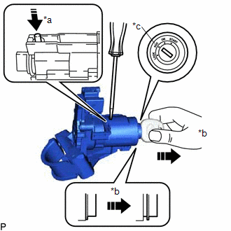
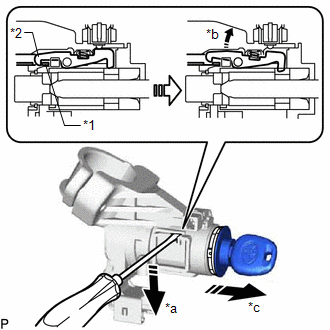
(b) Insert the tip of a screwdriver into the hole of the steering column upper bracket sub-assembly as shown in the illustration, and push out the ignition lock cylinder lock until its claw contacts the stopper at the top of the steering column upper bracket sub-assembly.
NOTICE:
Pull the ignition lock cylinder lock assembly until its claw contacts the stopper of the steering column upper bracket sub-assembly. Otherwise, the following procedure cannot be performed correctly.
(c) Insert the tip of a screwdriver into the hole of the steering column upper bracket sub-assembly and tilt it downward as shown in the illustration to release the claw of the ignition lock cylinder lock. Then, remove the ignition lock cylinder lock. |
|
4. REMOVE UNLOCK WARNING SWITCH ASSEMBLY (without Smart Key System)
(a) Insert the key. |
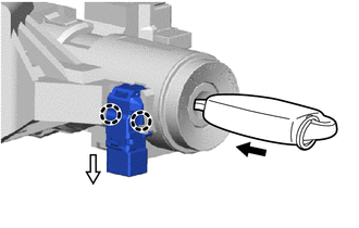 |
(b) Release the 2 claws to remove the unlock warning switch assembly.
5. REMOVE STARTER OR IGNITION SWITCH ASSEMBLY (without Smart Key System)
(a) Remove the 2 screws and the ignition or starter switch assembly. |
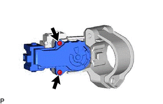 |
6. REMOVE KEY INTERLOCK SOLENOID (without Smart Key System)
(a) Remove the screw and key interlock solenoid from the steering column upper bracket sub-assembly. |
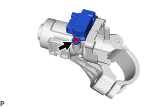 |
7. REMOVE STEERING LOCK ACTUATOR ASSEMBLY (with Smart Key System)
(a) Secure the steering column assembly in a vise between aluminum plates.
NOTICE:
Do not overtighten the vise.
(b) Using a center punch, mark the center of the shear bolt.
(c) Using a 3 to 4 mm (0.119 to 0.157 in.) drill, drill a hole in the bolt.
(d) Using a screw extractor, remove the bolt and steering lock actuator assembly from the steering column assembly. |
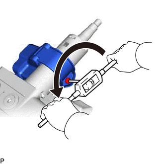 |
8. REMOVE POWER STEERING ECU ASSEMBLY
Click here
9. REMOVE ELECTRIC POWER STEERING MOTOR SHAFT DAMPER
Click here